Model 3158 High Power Biconical Antenna User Manual Model 3158 shown with pedestal
ETS-Lindgren L.P. reserves the right to make changes to any product described herein in order to improve function, design, or for any other reason. Nothing contained herein shall constitute ETS-Lindgren L.P. assuming any liability whatsoever arising out of the application or use of any product or circuit described herein. ETS-Lindgren L.P. does not convey any license under its patent rights or the rights of others. © Copyright 2000–2009 by ETS-Lindgren L.P. All Rights Reserved.
Table of Contents Notes, Cautions, and Warnings ................................................ v 1.0 Introduction .......................................................................... 7 ETS-Lindgren Product Information Bulletin ................................................... 8 2.0 Maintenance ......................................................................... 9 Annual Calibration .........................................................................................
This page intentionally left blank.
Notes, Cautions, and Warnings Note: Denotes helpful information intended to provide tips for better use of the product. Caution: Denotes a hazard. Failure to follow instructions could result in minor personal injury and/or property damage. Included text gives proper procedures. Warning: Denotes a hazard. Failure to follow instructions could result in SEVERE personal injury and/or property damage. Included text gives proper procedures.
This page intentionally left blank.
1.0 Introduction The ETS-Lindgren Model 3158 High Field Biconical Antenna is specifically designed for Immunity testing. This linearly-polarized transmit antenna is optimized to generate high levels of electromagnetic fields in the range of 20 MHz to 120 MHz. Model 3158 shown with pedestal The ability of the Model 3158 to handle high power levels over a broadband makes it excellent for use in Radiated Susceptibility testing. The biconical elements are made from welded aluminum tubing.
ETS-Lindgren Product Information Bulletin See the ETS-Lindgren Product Information Bulletin included with your shipment for the following: • Warranty information • Safety, regulatory, and other product marking information • Steps to receive your shipment • Steps to return a component for service • ETS-Lindgren calibration service • ETS-Lindgren contact information Introduction | 8
2.0 Maintenance Before performing any maintenance, follow the safety information in the ETS-Lindgren Product Information Bulletin included with your shipment. Maintenance of the Model 3158 is limited WARRANTY to external components such as cables or connectors. If you have any questions concerning maintenance, contact ETS-Lindgren Customer Service. Annual Calibration See the Product Information Bulletin included with your shipment for information on ETS-Lindgren calibration services.
Before performing any maintenance, disconnect the fiber optic cables from the unit and turn off power. When disconnecting fiber optic cables, apply dust caps to the ends to maintain their integrity. Before connecting fiber optic cables, clean the connector tips. Before attaching connectors, clean them with moisture-free compressed air. Failure to perform these tasks may result in damage to the fiber optic connectors or cables.
3.0 Specifications Electrical Specifications Frequency Range: 20 MHz to 120 MHz VSWR Ratio: • Typical—2:1 • Maximum—5:1 Maximum Input Power: 5 kW Input Impedance: 50 Ω Connector: 7/16 DIN female Physical Specifications 11 Length: 1.14 m (3.74 ft) Width: 3.00 m (9.84 ft) Height: 1.14 m (3.
This page intentionally left blank.
4.0 Assembly and Mounting Instructions Before connecting any components, follow the safety information in the ETS-Lindgren Product Information Bulletin included with your shipment.
The Model 3158 High Power Biconical Antenna is shipped unassembled, and includes these parts: • Balun • Biconical element (2) • Pedestal • Belleville washer (2) • Washer (4) and 5/16–1 1/4 hex bolt (4) • Air solenoid nylon tube • Fiber optic polarization cable Due to the size of the antenna, you must mount the balun onto the pedestal before you attach the elements. 1. Run your antenna cable through the polarization tube and attach it to the connector on the bottom of the balun.
2. Place the bottom of the balun in the mount plate. Insert two washers and two hex bolts on both sides of the mount plate to firmly secure the balun in place. Do not cross thread any connections or permanent damage could occur. 3. Slide a belleville washer onto the threaded screw end of one of the biconical elements. 4. Line up the screw threads on the element with the receptacle hole on the balun and turn the element until it is firmly secured in the balun. 5.
The Model 2090 (or next generation ETS-Lindgren controller, if applicable) is a separate component required for operation. 7. Connect the fiber optic polarization cable to the polarization unit located on the back of the pedestal. Connect the other end to the Model 2090 Multi-Device Controller.
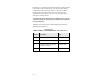
5.0 Typical Data All data was measured in an ETS-Lindgren FACT™ 3 chamber; field for a 5-kW input.
MIL-STD-461F/RTCA DO-160 SETUP (NO BENCH) Typical Data | 18
Data from ISO 11451-2 Setup 19 | Typical Data
ISO 11451-2 SETUP Typical Data | 20
Data from ECE Regulation 10 Setup Power input for 30 V/m at 2 meters from the antenna and 1 meter over the ground.
This page intentionally left blank.
Appendix A: Warranty See the Product Information Bulletin included with your shipment for the complete ETS-Lindgren warranty for your Model 3158. DURATION OF WARRANTIES FOR MODEL 3158 All product warranties, except the warranty of title, and all remedies for warranty failures are limited to two years.