
Operating instructions

A
3
/4” drain hose is located on the bottom side of the unit. The drain
may be extended for condensate removal to comply with local codes
(use fitting size or larger). Install a condensate trap on this line.
Electric heat is an option on H Series units and can be field-installed
on either single- or three-phase models.
Refer to the individual installation instructions for installing heater
kits on page 15.
The H Series units use an integrated defrost control to manage the
following control functions of the system:
1. Off and on functions of the outdoor fan during the defrost and
heating mode.
2. Off and on functions of the reversing valve during the defrost
and heating mode.
3. Off and on functions of the auxiliary heat relays during the
defrost mode.
The control is a time-and-temperature type with selectable
defrost
time intervals of 30, 60 and 90 minutes. Control circuit voltage at the
control is 24 volts input and output. The outdoor fan relay is SPNC
(single pole normally closed) and controls the fan motor.
COOLING MODE
Low-voltage thermostat terminal R is connected to Y and G, at the unit
low-voltage terminal board.
The system reversing valve is energized during the cooling mode.
Power is supplied to the reversing valve solenoid through the low-
voltage O terminal. The low-voltage Y terminal to the control will
energize the contactor latch coil (causing the contactor to energize the
compressor). The low-voltage Y terminal to the control will also
energize the control's timer. During the cooling mode, the defrost
thermostat is open (coil temperature is above 30°F) and will not allow
the time to be accumulated to initiate the defrost mode. The outdoor
fan is
wired through the N/C points of the control’
s relay and the N/O
points of the contactor. The fan motor will be energized whenever the
contactor is energized (except during defrost).
HEATING MODE
Low-voltage terminal R is connected to Y,G and O, at the unit low-
voltage terminal board.
The system reversing valve is powered during the heating mode. With
the thermostat system switch turned to heat, the low-voltage O
terminal is now energized, turning the reversing valve solenoid on
(switching the reversing valve to the heat position). The Y terminal will
energize the contactor and outdoor fan and the G terminal will
energize the indoor blower.
DEFROST MODE
To prevent ice build-up on the coil during the heating mode, as the
outdoor coil temperature falls below 30°F ± 5°F, an outdoor defrost
thermostat closes. (This thermostat is located on a coil tube.) When
the t
hermostat closes, the timer on the defrost control starts
accumulating the compressor run time. After the selected time (30, 60,
or 90 minutes) has been accumulated, the controller will start the
defrost cycle regardless of the outside temperature. During the defrost
cycle, the system is switched back into the cooling mode by the control
de-energizing the reversing valve solenoid. The N/C pole of the control
fan relay is opened, turning off the outdoor fan to allow the outdoor coil
to be warmed (defrosted) faster. The defrost control energizes the
indoor auxiliary heat relays through the E terminal to temper the indoor
supply air. This terminal should be connected to E (second-stage
heat) on the thermostat.
After the defrost thermostat reaches 65°F ± 5°F, the defrost cycle will
end. The control will not allow the defrost to continue longer than 10
minutes.
DEFROST TIME SELECTION
The defrost control has three selectable time intervals: 30, 60 and 90
minutes. The timing is factory set at 60 minutes. This timing has been
determined by testing to provide the best operating efficiency. In areas
where the humidity is lower than normal, the timer may be set to a higher
time (90 minutes). To change the time, move the timer jumper to the post
marked 30 for 30 minutes, 60 for 60 minutes, or 90 for 90 minutes.
DEFROST TEST POST
The defrost control has test posts to speed up the defrost time setting
by a factor of 256.
If you want to initiate a defrost without waiting for the time to
accumulate, you can jumper the two test pins (marked test). If the coil
temperature is above 30°F you will need to jumper the DFT (defrost
thermostat) terminals to simulate a closed thermostat. The defrost
cycle should occur in 7 seconds for a 30-minute setting, 14 seconds
for a 60-minute setting, and 17 seconds for an 90-minute setting. If the
jumper is removed immediately when the defrost cycle starts, the
cycle will end if the defrost thermostat is opened (coil above 65°F). If
the test pins remain jumped, and the defrost thermostat is closed, the
defrost will end in 2.3 seconds, which is the 10-minute default.
DURING THE ABOVE TEST, DO NOT CONTACT OR SHORT ANY
OTHER PIN. THIS MAY DAMAGE THE CONTROL.
FIELD CHARGING
Compared to a cooling-only unit, a heat pump is difficult to field charge
correctly without the use of charging scales. It is recommended the
charge be weighed in with an accurate charging scale. The correct
charge weight can be found on the unit name plate.
H Series units are equipped with a high-pressure switch. This switch is
wired through a lockout relay to lock out the system if the high side
pressure exceeds
425 psifor R22 and 600 psi for R410A. The high
side pressure MUST be below 300 psi for R22 and 450 for R410A
before the system can be reset.
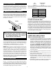
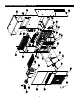
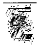
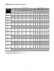
L. ELECTRICAL HEAT INSTALLATION
FIGURE 2
Unit Model A B
18/24 35 71
30/36 39 71
48/60 42 86
1
/2
MOUNTING FLANGE BOLT
PATTERN DIMENSIONS
5
M. DEFROST CONTROL
N.
BASIC SEQUENCE OF OPERATION
O. HIGH-PRESSURE LOCK OUT
K. CONDENSATE DRAIN
A TWO-STEP THERMOSTAT MUST BE USED IF AN
ELECTRIC HEATER IS INSTALLED.