
Unit installation


The installer SHALL comply with all local, state, and federal codes
and/or regulations pertaining to this type of equipment and its
installation. Such codes and/or regulations should take precedence
over any recommendations contained herein in lieu of local codes.
Installations SHALL be made in accordance with the National
Electrical Code, local codes, and recommendations made by the
National Board of Fire Underwriters.
1. To eliminate noise from being transmitted into noise-sensitive
areas, the unit should NOT be installed on walls adjoining
bedrooms, sleeping quarters, or adjacent to windows.
2. Locating the unit as close as possible to the main duct
system or area to be conditioned, will prevent lengthy duct
runs and unnecessary thermal and air-pressure losses.
3. The clearance to combustibles is 0
" on all sides, and
1
/4" for
the first three (3) feet of supply duct.
4. The condenser air inlets (left, right and bottom inlets) SHALL
be located at least 8
" away from walls or other obstructions
for unrestricted airflow.
5. The condenser air outlet should be located at least 6’ away
from any obstructions to prevent recirculation of condenser
air.
6. Service clearance is 28
" from the electrical box access panel
located on the front of the unit and 28
" from the center, upper,
and lower front access panels.
7. The wall selected for unit installation MUST be able to or be
made to safely support the weight of the unit.
8. Do NOT locate where heat, lint or exhaust fumes will be
discharged on the unit (as from dryer vents).
1. The H Series model units have top rain flashing built onto the
unit. The bottom-mounting flange for all models is shipped
separately and in place. (Refer to “Section J. Unit Installation”
for the recommended use of the bottom flange.)
2. Electrical entrances are located on the right side, left side,
and back of all H Series units. Refer to “Section H. Electrical
Hook-up” for details.
3. Return and supply air collars and air gaskets are factory
installed.
4. The supply and return air ducts should be checked to be sure
they:
a. Match the openings on the unit to be installed.
b. Have the same distance between them vertically as the
openings on the unit to be installed.
5. If the factory-installed filter is used on your installation,
access to the filter is made through the center panel on the
front of the unit. IF A REMOTE FILTER IS USED, SUCH AS
A FILTER GRILLE, THE FACTORY-INSTALLED FILTER
MUST BE REMOVED AND DISCARDED.
1. Properly-sized duct systems are critical for satisfactory
operation of any heat pump system. All ductwork MUST be
correctly sized for the design air flow requirement of the
equipment.
2. The recommended operation duct static is to deduct
0.07
" W.C. for any size of heater 5 kW to 20 kW on factory- or
field-installed heaters.
3. Ductwork routed through wall cavities, as well as any duct not
in conditioned space, MUST be insulated. Supply ducting
routed through exterior walls MUST be insulated with 1
"
insulation to the back of the unit.
4. Supply and return air ducts should be flush with the exterior
wall and sized to fit over the unit duct collars in order to
compress the collar air gasket.
5. If supply duct is flashed to the exterior of a building
constructed with combustible material, the flashing MUST be
insulated in order to maintain the required clearances to
combustible materials. Required clearance is
1
/4" for the first
three (3) feet of supply duct.
1. One-inch disposable filters are supplied standard in each
unit. Two-inch disposable filters can also be used and are
available as an option. The filter rack is adjustable to
accommodate 2
" filters. The filter rack on this series is
adapted by bending the retaining brackets. Refer to the
Maintenance section on page 3 for the procedures for
changing the filters.
2. If a filter grille is used in the installation, the filter should be
properly sized to allow a maximum velocity of 400 FPM.
THE FACTORY-INSTALLED FILTER MUST BE
REMOVED.
The installer MUST check available power to make certain it
matches the unit nameplate rating and that constant voltage can be
maintained to the unit. Unsatisfactory and unsafe performance
could otherwise result. The local power company should be
contacted about questions concerning power supply.
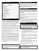
These units are standard equipped from the factory with a unit
disconnect. This is in the form of a circuit breaker (230V models) or
a disconnect (460V models). If an optional electric heat kit is to be
installed, follow the instructions included with the heater assembly.
See Figure 1 for reference.
FIGURE 1
Electrical Box
Breaker
Breaker Mount
B. UNIT SITE LOCATION
A. CODES
INSTALLATION
C. UNIT PREPARATION
D. DUCTWORK
E. FILTERS
F. ELECTRICAL POWER
G. BREAKER/DISCONNECT ASSEMBLY
4