
Installation Manual


- ix -
EUCAST Co. Ltd. All rights Reserved
= CONFIDENTIAL =
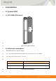
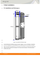
1) RF Antenna : Inside the enclosure, ANT1/ANT2
145
2) Backhaul Port(RJ45) : It is used for connection with B / H and supports Ethernet
146
(100/1000 Base-T)
147
3) Daisy-chain Port(RJ45) : It is used for connection with B / H another base station and
148
supports Ethernet (100/1000 Base-T)
149
4) LMT Port(RJ45) : It is used for operation management in field and supports Ethernet (10 /
150
100Base-T)
151
5) GPS ANT(SMA Female) : It connects to GPS antenna. Support +5VDC for external GPS
152
active antenna.
153
6) DC IN Port : This is +12VDC DC Power Input Port.
154
7) Status LED : System Status LED
155
156
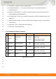
1.1.5.2 Detailed Definition of Interface
157
No
Name
Connector Type
To/From
Descriptions
1
DC IN
RAPC712X
Jack
AC/DC
adaptor
@+12 VDC
Cable Side :
Outer Diameter 5.5mm
Inner diameter 2.5mm
2
ETH LMT
RJ45 receptacle
LMT
10/100Base-T
Cable Side : RJ45 Plug
3
ETH B/H
RJ45 receptacle
Backhaul
10/100/1000Base-T
Cable Side : RJ45 Plug
4
ETH D/A
RJ45 receptacle
Other BS B/H
10/100/1000Base-T
Cable Side : RJ45 Plug
5
GPS
SMA(F)
GPS Antenna
GPS Ant Cable : SMA(M)
Table 4. Interface overview
158
159
160
161
162