
Operating Instructions


9
2112657-15-06/20 (translation of the original operating instructions)
Operating Instructions Safety Systems
MGB-L0…-AR.-… and MGB-L0…-AP.-…
EN
7. System overview
7.1. Interlocking module MGB-L0-…
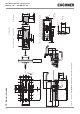
2
3
4
1
7
6 5
Key:
1 Cover for auxiliary release
2 LED indicator
3 DIP switches
4 Terminals X2 -X5
5 Depending on version:
Cable entry M20x1.5 or plug connector
6 Internal reset
7 Auxiliary marking for maximum permitted mounting distance
Notice:
Depending on the version, additional controls and indicators may be integrated into
the cover and a mounting plate can be included.
See enclosed data sheet.
Figure 1: Interlocking module MGB-L.--…
7.2. Handle module MGB-H-…
1
2
5
4
2
3
4
Key:
1 Door handle
2 Fold-out lockout mechanism
(optional: second, automatically extending lockout mechanism)
3 Locking pin for handle adjustment
4 Locking screws T10 for housing cover
5 Bolt tongue
Notice:
Depending on the version, a mounting plate can be included.
See enclosed data sheet.
Figure 2: Handle module MGB-H-…
7.3. Escape release MGB-E-… (optional)
1 2 3 4
Key:
1 Door handle
2 Cover
3 Actuation axis 8 x 8 mm
(different lengths available)
4 Protective sleeve
Notice:
Depending on the version, a mounting plate can be included.
See enclosed data sheet.
Figure 3: Escape release MGB-E-…