
Operating Instructions


Operating Instructions Safety Systems
MGB-L1…-AR.-… / MGB-L2…-AR.-… and MGB-L1…-AP.-… / MGB-L2…-AP.-…
10
(translation of the original operating instructions) 2119167-06-06/20
6. Function
Together with a handle module, the locking module makes it possible to lock movable guards. The combination also serves
as a mechanical door stop at the same time.
DIP
OFF
ON
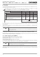
The following switch-on condition applies to the safety outputs FO1A and FO1B (also see chapters 15.2. System
status table MGB-AR on page 39 and 15.3. System status table MGB-AP on page 40):
Conguration
System family MGB-AR MGB-AP
Guard locking monitoring active inactive active inactive
Condition
No fault in the device TRUE TRUE TRUE TRUE
Guard closed TRUE TRUE TRUE TRUE
Bolt tongue inserted in locking module TRUE TRUE TRUE TRUE
Guard locking active TRUE Not relevant TRUE Not relevant
In case of series connection:
Signal available from the upstream switch on the safety inputs FI1A and
FI1B
In case of separate operation:
DC24V present at the safety inputs FI1A and FI1B
TRUE TRUE Not relevant Not relevant
FO1A and FO1B are ON
The locking module detects the position of the guard and the position of the bolt tongue. The position of the guard locking
is also monitored.
Guard locking monitoring can be deactivated using DIP switches (see chapter 12.6. Changing device conguration (using
DIP switches) on page 26).
Important!
For use as guard locking for personnel protection in accordance with ENISO14119, guard locking
monitoring must be active.
The bolt tongue in the handle module is moved into and out of the locking module by actuating the door handle.
When the bolt tongue is fully inserted in the locking module, the locking arm locks the bolt tongue in this position. Depending
on the version, this locking is by spring force or solenoid force.
6.1. Guard locking for version MGB-L1
(Guard locking actuated by spring force and released by power-ON)
Activating guard locking: close guard; no voltage at the solenoid.
Releasing guard locking: apply voltage to the solenoid.
The spring-operated guard locking functions in accordance with the closed-circuit current principle. If the voltage is interrupted
at the solenoid, the guard locking remains active and the guard cannot be opened directly.
Important!
If the guard is open when the power supply is interrupted and is then closed, guard locking is activated.
This can lead to persons being locked in unintentionally.
As long as the locking arm is closed, the bolt tongue cannot be pulled out of the locking module and the guard is locked.
When voltage is applied to the guard locking solenoid, the locking arm is opened and bolt tongue is released. The guard
can be opened.