
Operating Instructions


9
2537377-02-07/21 (translation of the original operating instructions)
Operating Instructions
Transponder-Coded Safety Switch CTP/CTA-L1/2-BP
EN
6.2.7. Communication connection C
A monitoring output with the sufx C has the additional function of providing a communication connection to a BR/IO-Link
Gateway. The switch delivers cyclical and acyclical data. You will nd an overview of the communication data in chapter 11.
Using communication data on page 21.
If no BR/IO-Link Gateway is connected, this output behaves like a monitoring output.
6.3. Version CTP/CTA Extended
Devices in the Extended version contain additional controls/indicators in the housing cover. Please refer to the enclosed
data sheet for further information.
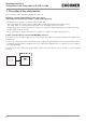
6.4. Guard locking
6.4.1. Guard locking on version CTP/CTA-L1
(guard locking actuated by spring force and released by power-ON)
Activating guard locking: close guard; no voltage at the solenoid.
Releasing guard locking: apply voltage to the solenoid.
The spring-operated guard locking functions in accordance with the closed-circuit current principle. If the voltage is interrupted
at the solenoid, the guard locking remains active and the guard cannot be opened directly.
Important!
If the guard is open when the power supply is interrupted and is then closed, guard locking is activated.
This can lead to persons being locked in unintentionally.
The actuator cannot be pulled out of the switch and the guard is locked as long as the guard locking pin is extended.
If a voltage is applied to the guard locking solenoid, the guard locking pin is retracted and the actuator is released. The
guard can be opened.
6.4.2. Guard locking on version CTP/CTA-L2
(guard locking actuated by power-ON and released by spring force)
Important!
Use as guard locking for personnel protection is possible only in special cases, after strict assessment
of the accident risk (see ENISO14119:2013, section 5.7.1)!
Activating guard locking: apply voltage to the solenoid.
Releasing guard locking: disconnect voltage from the solenoid.
The magnetically actuated guard locking operates in accordance with the open-circuit current principle. If the voltage is
interrupted at the solenoid, the guard locking is released and the guard can be opened directly!
The guard can be opened as long as no voltage is applied to the guard locking solenoid.
If a voltage is applied to the guard locking solenoid, the guard locking pin is held in the extended position and the guard is
locked.