AS-i Safety Monitor for 2 AS-i circuits User Manual Revision date: 2008-10-24
Subject to modifications without notice. Generally, this manual refers to products without mentioning existing patents, utility models, or trademarks. The absence of any such references does not indicate that a product is patent-free. © Euchner GmbH + Co. KG Kohlhammerstr.
AS-i Safety Monitor for 2 AS-i circuits Table of contents Table of contents AS-i Safety Monitor for 2 AS-i circuits 1 1.1 2 Symbol catalog ..................................................................................... 9 Abbreviations ................................................................................................... 9 General ................................................................................................ 10 2.1 Product information................................
AS-i Safety Monitor for 2 AS-i circuits Table of contents 5.6 Commissioning .............................................................................................. 21 5.6.1 5.6.2 5.6.2.1 5.6.2.2 5.6.3 5.6.4 5.6.5 5.7 6 6.1 7 7.1 7.1.1 Supply voltage for AS-I Safety Monitor ....................................................................... 21 Duplicate address recognition .....................................................................................
AS-i Safety Monitor for 2 AS-i circuits Table of contents 8.7.1 8.7.1.1 8.7.1.2 8.7.1.3 8.7.1.4 8.7.1.5 8.7.1.6 8.7.1.7 8.7.1.8 8.7.1.9 8.7.1.10 8.7.1.11 8.7.1.12 8.7.1.13 8.7.1.14 8.7.2 9 Unsafe data.................................................................................................................... 44 Card unformatted ......................................................................................................... 44 Data not compatible ...........................................
AS-i Safety Monitor for 2 AS-i circuits Table of contents 10 Configuration mit Windows Software ASIMON 3 G2 ...................... 79 11 Diagnostics for AS-i Monitor and networking using AS-i Master.. 80 11.1 Introduction .................................................................................................... 80 11.2 On-location operation .................................................................................... 80 11.3 Spontaneous messages ...................................
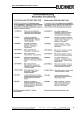
AS-i Safety Monitor for 2 AS-i circuits Declaration of Conformity Declaration of Conformity Subject to reasonable modifications due to technical advances Kohlhammerstraße 16 • D-70771 Leinfelden-Echterdingen Id.-No.: 103336 Issue date - 24.10.2008 EUCHNER GmbH + Co. KG Tel. +49/711/75 97-0 • Fax.
AS-i Safety Monitor for 2 AS-i circuits 8 Subject to reasonable modifications due to technical advances Kohlhammerstraße 16 • D-70771 Leinfelden-Echterdingen Id.-No.: 103336 Issue date - 24.10.2008 EUCHNER GmbH + Co. KG Tel. +49/711/75 97-0 • Fax.
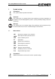
AS-i Safety Monitor for 2 AS-i circuits Symbol catalog 1. Symbol catalog Information! This symbol indicates important information. Attention! This symbol warns of a potential failure. Non-compliance may lead to interruptions of the device, the connected peripheral systems, or plant, potentially leading to total malfunctioning. Warning! This symbol warns of an imminent danger. Non-compliance may lead to personal injuries that could be fatal or result in material damages and destruction. 1.
AS-i Safety Monitor for 2 AS-i circuits General 2. General 2.1 Product information This system manual applies to the following Euchner GmbH + Co. KG equipment: AS-i Safety Monitor for 2 AS-i circuits RS 232 diagnostic port 103303 Tab. 2-1. The AS-i Safety Monitor in a stainless steel enclosure is an E-STOP switching device which monitors safety configured slaves and correct function of the network. The safety unit provides 4 inputs which can be defined as either EDM or as START inputs.
AS-i Safety Monitor for 2 AS-i circuits General 2.2 Brief description The Actuator-Sensor-Interface (AS-i) has been established as a system for networking primarily binary sensors and actuators on the lowest level of the automation hierarchy. The large number of installed systems, ease of use and reliable operating behavior make AS-i also ideal for machine safety applications. The safe AS-i system is intended for safety applications up to Category 4/SIL 3.
AS-i Safety Monitor for 2 AS-i circuits General 2.3 Conformity statement The AS-i Safety Monitor for 2 AS-i circuits has been developed and manufactured in accordance with the applicable european standards and directives. Information! The corresponding conformity statement can be found at the very beginning of this system manual. 2.4 Certification according to DIN EN ISO 9001 : 2000 The manufacturer of the product possesses a certified quality assurance system in accordance with ISO 9001.
AS-i Safety Monitor for 2 AS-i circuits Safety 3. Safety 3.1 Safety standard The AS-I Safety Monitor has been developed, manufactured, tested and submitted for type testing in accordance with the safety standards prevailing at the time of testing. The safety requirements per Category 4 in accordance with EN 954-1 and Performance Level “e” in accordance with EN ISO 13 849-1 are met by all devices.
AS-i Safety Monitor for 2 AS-i circuits Safety The device also assumes the mandatory E-STOP function (Stop Category 0 or 1) for all non-manually operated machines, dynamic monitoring of the restart function and the protection monitoring function. Examples for use of the AS-I Safety Monitor: The device is used economically in machines and equipment in which the standard AS-I bus is the local bus.
AS-i Safety Monitor for 2 AS-i circuits Safety 3.3.4 Qualified personnel Installation, commissioning and maintenance of the devices are to be performed only by qualified specialists. Electrical work is to be performed only by electrical technicians. Setting and changing the device configuration via PC and ASIMON 3 G2 configuration software are to be performed only by an authorized safety representative.
AS-i Safety Monitor for 2 AS-i circuits Spezifications 4. Spezifications 4.1 Technical data Attention! The AS-I power supply for the AS-I components must have isolation per IEC 60 742 and be able to handle momentary power interruptions of up to 20 ms. The power supply for the 24 V supply must also have isolation per IEC 60 742 and be able to handle momentary power interruptions of up to 20 ms. The maximum output voltage of the power supply must also be less than 42 V in case of a fault. 4.1.
AS-i Safety Monitor for 2 AS-i circuits Spezifications 103303 Electrical data 24 V DC (26,5 … 31,6 V out of AS-i) Operating voltage Operating current approx. 200 mA out of 24 VDC and approx.
AS-i Safety Monitor for 2 AS-i circuits Spezifications 4.2 Consideration of failure probability according to IEC 61 508 To allow calculation of failure probability for the entire system, the AS-i Safety Monitor returns a component which depends on the maximum uninterrupted switch-on time of the output circuit(s).
AS-i Safety Monitor for 2 AS-i circuits Installation 5. Installation 5.1 Dimensions Warning! Cover the top of the AS-I Safety Monitor when doing any drilling work above the unit. No particles, especially metal chips, should be allowed to enter the housing, since this could cause a short circuit. Information! For additional information, please refer to . 5.2 Connections 0,8 Nm 7 LB.IN 5 ... 6 mm / PZ2 10 2 2 x (0,5 .... 1,5) mm 10 2 2 x (0,5 ....
AS-i Safety Monitor for 2 AS-i circuits Installation 5.3 Installing in the control cabinet The AS-I Safety Monitor is installed in the control cabinet on 35mm DIN rails per DIN EN 50 022. Information! The enclosure of the AS-i Safety Monitor is made of stainless steel. The unit is also suitable for exposed wall mounting. To install, place the unit on the upper edge of the DIN rail and then snap in the lower edge. [1] [2] + 5.
AS-i Safety Monitor for 2 AS-i circuits Installation 5.5 Electrical Connection Information! Electrical connections are described in section 5.6 Commissioning 5.6.1 Supply voltage for AS-I Safety Monitor Supply by AS-i Redundant: supply out of AS-i... ...or out of 24 V aux. power AS-i AS-i 24 V, 0 V ... or out of AS-i 2 AS-i 1 5.6.2 Duplicate address recognition 5.6.2.
AS-i Safety Monitor for 2 AS-i circuits Installation 5.6.2.2 AS-i Master with duplicate address recognition Gateway Monitor AS-i 1 Power supply Power supply PWR 1 PWR 2 AS-i 2 Duplicate address recognition in the AS-i Master active 22 Subject to reasonable modifications due to technical advances Kohlhammerstraße 16 • D-70771 Leinfelden-Echterdingen Id.-No.: 103336 Issue date - 24.10.2008 EUCHNER GmbH + Co. KG Tel. +49/711/75 97-0 • Fax.
AS-i Safety Monitor for 2 AS-i circuits Installation 5.6.3 Replacing the chip card Always turn off power before inserting or removing the card! [1] [2] [3] [4] [5] alt/old/ancien/ vecchia/anciano [6] [7] neu/new/neuve/ [8] Subject to reasonable modifications due to technical advances Kohlhammerstraße 16 • D-70771 Leinfelden-Echterdingen Id.-No.: 103336 Issue date - 24.10.2008 EUCHNER GmbH + Co. KG Tel. +49/711/75 97-0 • Fax.
Kohlhammerstraße 16 • D-70771 Leinfelden-Echterdingen Subject to reasonable modifications due to technical advances Id.-No.
Subject to reasonable modifications due to technical advances Kohlhammerstraße 16 • D-70771 Leinfelden-Echterdingen Id.-No.
AS-i Safety Monitor for 2 AS-i circuits Installation 5.6.5 Replacing a defective safety-configured AS-i slave The new slave must be able to send teaching codes and must have the same address as the old one. Only one missing slave is allowed! [1] [2] ESC/Service (3 seconds) [3] CONNECT N E W S L AV E 1 7 THEN PRESS SERVICE [4] ESC/Service (3 seconds) 26 Subject to reasonable modifications due to technical advances Kohlhammerstraße 16 • D-70771 Leinfelden-Echterdingen Id.-No.
AS-i Safety Monitor for 2 AS-i circuits Installation 5.7 Safe configuration using ASIMON 3 G2 ASIMON 3 G2 Software Start Before commissioning the safety unit, put the gateway into operation! ASIMON 3 G2 Software Change the preset password during the first use of the device (Monitor/change password)! ASIMON 3 G2 Software Create the desired configuration. ASIMON 3 G2 Software Download the configuration with MONITOR / PC-> MONITOR into the device. Enter the password for this purpose.
AS-i Safety Monitor for 2 AS-i circuits Installation ASIMON 3 G2 Software ☺Press OK for Menu Output Circuit 1:ON 2:OFF The device is in the protected mode now.
AS-i Safety Monitor for 2 AS-i circuits Maintenance 6. Maintenance 6.1 Checking for safe turn-off The safety representative is responsible for checking flawless function of the AS-i Safety Monitor within the safety system. Safe turn-off when an associated safe sensor or switch is triggered must be checked at least once a year. Attention! To do this, actuate each safe AS-i slave and observe the switching behavior of the output circuits of the AS-i Safety Monitor.
AS-i Safety Monitor for 2 AS-i circuits Electrical connection 7. Electrical connection 7.1 Overview of terminals, indicators and operating elements 7.1.1 103303 [3] [7] [4] [3] [5] [7] [6] + - + - + - [1] 5 ... 6 mm / PZ2 0,8 Nm 7 LB.IN 10 2 2 x (0,5 .... 1,5) mm 10 [2] 2 2 x (0,5 .... 1,5) mm AWG 2 x 24 ...12 Legend: [1] Chip card slot [2] RS 232 diagnostics port1 [3] LEDs [4] LC display [5] Buttons [6] Terminals: Supply voltage and AS-i circuit [7] Terminals: Safety Monitor 1.
AS-i Safety Monitor for 2 AS-i circuits Electrical connection 7.2 AS-i bus connection Blue AS-i- Yellow ASi ribbon cable Braun AS-i+ Blau AS-i- Brown AS-i+ 2-conductor AS-i round cable (Recommended: flexible power cable H05VV-F2x1,5 per DIN VDE 0281) Information! Electrical work is to be performed only by electrical technicians. 7.3 Information about the device types Information! A listing of the individual devices and their features can be found in section . 7.
AS-i Safety Monitor for 2 AS-i circuits Electrical connection 7.4.1 Electrical connection 103303 + - + - + - +ASI 1– ASI 1 +PWR– (max. 4A) +ASI 2– + 2 +PWR– (max. 4A) ASI Terminal Signal / Description +ASI 1– Connection to AS-i Circuit 1 +ASI 2– Connection to AS-i Circuit 2 ASI 1 +PWR– Supply voltage for AS-i Circuit 1 (max. 4 A) ASI 2 +PWR– Supply voltage for AS-i Circuit 2 (max. 4 A) FG Function ground Information! AS-i Circuits 1 and 2 are powered by separate power supplies.
AS-i Safety Monitor for 2 AS-i circuits Electrical connection 7.5 Diagnostics interface The service and diagnostics interface (in conjunction with AS-i Control Tools or ASIMON 3 G2 software) is used for communication between the PC and the unit. 7.5.1 103303 The service and diagnostics interface in these devices is configured as a mini DIN-6 female and it is placed on the front plate, on the left hand side. 7.
AS-i Safety Monitor for 2 AS-i circuits Electrical connection 7.7 Release circuits 7.7.1 Wiring overview of Safety Monitor 103303 1.13 0 V 24 V 2.13 2.Y2 + 2.Y1 + Aux 1.Y1 1.Y2 2.Y1 2.Y2 K1 K2 K3 K4 + 1.Y1 + 1.Y2 1.14 3.14 4.14 2.14 1.Y1 (EDM 1/Start 1), 2.Y1 (EDM 2/Start 2), 1.Y2 (EDM 3/Start 3), 2.Y2 (EDM 4/Start 4) The safety unit provides 4 inputs. The EDM & START inputs can be defined freely.
AS-i Safety Monitor for 2 AS-i circuits Electrical connection 7.8 Indicators and operating elements 7.8.1 LED indicators – Monitor 103303 ad y AS -i 1 U AS -i 2 U re fa ul t chip card The LED’s on the front panel of the device indicate: power The monitor is receiving sufficient power.
AS-i Safety Monitor for 2 AS-i circuits Electrical connection 7.8.2 LED indicators safety unit in 103303 1.13 0 V 24 V 2.13 2.Y2 + 2.Y1 + Aux 1.Y1 1.Y2 2.Y1 2.Y2 K1 K2 K3 K4 + 1.Y1 + 1.Y2 1.14 3.14 4.14 2.14 The LED’s on the safety unit indicate: Aux 24 V supply for the semiconductor outputs is present. 1Y.1, 1Y2, 2Y.1, 2Y.2 Input 1.Y1 (EDM 1/Start 1), 2.Y1 (EDM 2/Start 2), 1.Y2 (EDM 3/Start 3), 2.Y2 (EDM 4/Start 4) is turned on. K1, K2 Contact sets 1.13, 1.14 (K1) resp. 2.13, 2.14 (K2) closed.
AS-i Safety Monitor for 2 AS-i circuits Electrical connection 7.8.3 Buttons The buttons are used for the following: ⇑ Navigation in extended mode ⇓ OK Change to extended mode ESC/Service For teaching the code table for a new safe slave, when exactly one safe slave is being replaced, and for unlocking the Safety Monitor. This button is also used to exit extended mode.
AS-i Safety Monitor for 2 AS-i circuits Function and startup of the Safety Monitor 8. Function and startup of the Safety Monitor Configuration and startup of the AS-i Safety Monitor is accomplished using a PC/ Notebook and the ASIMON 3 G2 configuration software. The operating language of the device can be set for the respective country (see section ).
AS-i Safety Monitor for 2 AS-i circuits Function and startup of the Safety Monitor In contrast to the master configuration, the complete configuration also contains the code sequences for all included slaves. Sending the complete configuration from the chip card to the Safety Monitor can make replacement of the device enormously simpler and faster. Information! For additional information refer to . 8.2.
AS-i Safety Monitor for 2 AS-i circuits Function and startup of the Safety Monitor 8.2.
AS-i Safety Monitor for 2 AS-i circuits Function and startup of the Safety Monitor Attention! Safety advisory: Power must always be turned off when removing or inserting the chip card! Ensure that the chip card contains the configuration intended for and released for the application! This can be done by comparing the release codes on the display (section): The safety representative who generated and validated the release code stores the release code for the master configuration and approves
AS-i Safety Monitor for 2 AS-i circuits Function and startup of the Safety Monitor • ASIMON software over diagnostic port • AS-i Control Tools over diagnostic port The following diagnostics can be displayed (see section ): 8.4.
AS-i Safety Monitor for 2 AS-i circuits Function and startup of the Safety Monitor Information! For additional information see section. • A PIN is a 4-digit number and can only be changed from the display, not via the ASIMON 3 G2 software. • After entering the PIN, the display can be used to start a teaching procedure for the code sequences. The monitor stops immediately after entering the PIN.
AS-i Safety Monitor for 2 AS-i circuits Function and startup of the Safety Monitor • Briefly pressing the ESC/Service key unlocks the Safety Monitor when red is flashing • A longer press (3s) starts the teach procedure for a slave. Information! For additional information see section . 8.
AS-i Safety Monitor for 2 AS-i circuits Function and startup of the Safety Monitor 8.7.1.2 Data not compatible If a card is found whose data are incompatible with the device, the following error message is displayed: NEW CHIPCARD WILL BE FORMATED AS-I DATA WILL BE SYNCHRONIZED 8.7.1.3 Card empty The following message is displayed for an empty card: CHIPCARD FOUND AS-I DATA WILL BE SYNCHRONIZED From this time on all changes are made both in the device and on the chip card. 8.7.1.4 8.7.1.
AS-i Safety Monitor for 2 AS-i circuits Function and startup of the Safety Monitor 8.7.1.7 Data in the device and on the chip card not identical If the card and device are not empty at start and the data are not identical, an error message is displayed and the card is not synchronized with the device.
AS-i Safety Monitor for 2 AS-i circuits Function and startup of the Safety Monitor CHIPCARD FOUND. SAFETY DATA WILL BE SYNCHRONIZED 8.7.1.
AS-i Safety Monitor for 2 AS-i circuits Function and startup of the Safety Monitor ERROR. CHIPCARD AND SAFETY DATA DIFFERENT. DELETE CHIPCARD OR SAFETY DATA The safety unit will not operate in this case. You must either clear the device or the active bank via menu. 8.7.1.14 Operating the chip card from the menu The data on the chip card can, as described in section , be exchanged between the Monitor and the chip card.
AS-i Safety Monitor for 2 AS-i circuits Function and startup of the Safety Monitor Attention! Safety advisory: Ensure that the configuration intended for and released for the application is used! This can be done by comparing the release codes on the display (See section ): The safety representative who generated and validated the configuration stores the release code for the configuration (Complete or Master) stores the release code for the configuration and approves use of the configurati
AS-i Safety Monitor for 2 AS-i circuits Operation in advanced display mode 9. Operation in advanced display mode Information! From SETUP/LANGUAGE you can set the desired menu language (German, English, French, Italian or Spanish), see . 9.1 Overview classic mode / klassischer Modus Commissioning / Inbetriebnahme underlined data can be edited unterstrichene Werte sind editierbar .
AS-i Safety Monitor for 2 AS-i circuits Operation in advanced display mode classic mode / klassischer Modus Commissioning / Inbetriebnahme .
AS-i Safety Monitor for 2 AS-i circuits Operation in advanced display mode 9.2 Navigation in advanced mode AS-I SAFETY DIAGNOSTICS SETUP ☺ Meennuu ☺ P r e s s O K f o rr M LCD CONTRAST Output Circu u ii tt 1:ON 3:ON 2:ON FF 4:ON The device starts up in traditional (classical) mode. Switch to advanced mode by pressing the OK key. From advanced mode you can return to traditional mode by repeatedly pressing the ESC/Service key.
AS-i Safety Monitor for 2 AS-i circuits Operation in advanced display mode 9.
AS-i Safety Monitor for 2 AS-i circuits Operation in advanced display mode TEACH CODES ENTER PIN 0000 OK If the PIN was correctly entered, the Monitor is stopped and the following information appears: TEACHING CODES CLOSE CONTACTS AS-I 1: |1-OK 2-RX | 3-RR .... | 30-DC |31-DC AS-I 2: | 1-OK 2-RX | 3-RR .... | 30-DC |31-DC .... HELP NO SAFETY SL MS MISSING SLAVE X CH OK R CH RELEASED OK CODE LEARNED ER CODE ERROR DC DUPL.
AS-i Safety Monitor for 2 AS-i circuits Operation in advanced display mode START MONITOR? OK Information! See also . 9.3.1.2 SINGLE SLAVE Main Menü || AS-I SAFETY || TEACH CODES || SINGLE SLAVE || This menu point allows you to teach the code table for a safe slave.
AS-i Safety Monitor for 2 AS-i circuits Operation in advanced display mode • Confirm with OK (display flashes) • Use the arrow keys to enter the desired address • Confirm with OK (display stops flashing) • Use one of the two arrow keys to exit the input screen • Save with OK, or cancel the process by pressing ESC. Information! Be sure that all slave contacts on the corresponding slave are closed. The teaching procedure was successful if an OK appears in the third line.
AS-i Safety Monitor for 2 AS-i circuits Operation in advanced display mode The teach procedure was successful if after approx. 2 s an OK appears in the display. COUPLING SLAVE SLAVE ADDR. ––1 ESC [OK] Save with OK, or cancel the process by pressing ESC. 9.3.1.4 INPUT CODE SEQ. Main Menu || AS-I SAFETY || TEACH CODES|| INPUT CODE SEQ. || This menu point allows you to directly enter the code sequence for a particular AS-i safety slave.
AS-i Safety Monitor for 2 AS-i circuits Operation in advanced display mode 9.3.2 SAFE OUTPUT CH (channels for the release circuits) Main Menu || AS-I SAFETY || SAFE OUTPUT CH || SAFE OUTPUT CHANNELS CH 1: ON CH 2: OFF ... CH 16: OFF In this menu you can read off the status of the 16 release circuits. 9.3.
AS-i Safety Monitor for 2 AS-i circuits Operation in advanced display mode START/STOP STOP CHANGE In this menu you change the mode of the Monitor. START: STOP: 9.3.5 Sets the Monitor to protecting operating mode Sets the Monitor to configuration mode CLEAR SAFE CFG (delete safe configuration) Main Menu|| AS-I SAFETY || CLEAR SAFE CFG || CLEAR SAFE CFG ENTER PIN 0000 OK In the CLEAR SAFE CFG menu the stored safe information is deleted. This procedure is PIN protected. 9.3.
AS-i Safety Monitor for 2 AS-i circuits Operation in advanced display mode Information! The default setting for the PIN is “0000” and must not be changed. 9.3.7 SAFE CHIPCARD Main Menu || AS-I SAFETY || SAFE CHIPCARD || SAFE CHIPCARD ACTIVE: BANK B VIEW CARD -> MONITOR MONITOR -> CARD CLEAR CODES CLEAR SAFE CARD In this menu you can manage the safe area of the chip card. ACTIVE: BANK X VIEW: Reads out the safety configuration of a chip card bank.
AS-i Safety Monitor for 2 AS-i circuits Operation in advanced display mode BANK A CONFIG RELEASE DATE: 2006/06/17 18:43 BY: ROLF BECKER CONFIG NAME: L3040 MIT LADEVO RRICHTUNG LINK U ND PALETTENWECHS LER V1.23 RELEASE CODE: 1BDF After selecting the desired memory bank and confirming with OK, the configuration is displayed. For additional information refer to . 9.3.7.
AS-i Safety Monitor for 2 AS-i circuits Operation in advanced display mode STOP MONITOR OK COPY BANK A to MONITOR RELEASE DATE: 2006/06/17 18:43 BY: ROLF BECKER CONFIG NAME: L3040 MIT LADEVO RRICHTUNG LINKS U ND PALETTENWECHS LER V1.23 RELEASE CODE: 1BDF --------------TYPE CODE 1BDF OK START MONITOR OK In this menu you send the safe configuration stored on the memory card to the EEPROM on the Monitor. Use the keys to set the release code and confirm with OK.
AS-i Safety Monitor for 2 AS-i circuits Operation in advanced display mode 9.3.7.
AS-i Safety Monitor for 2 AS-i circuits Operation in advanced display mode 9.3.7.
AS-i Safety Monitor for 2 AS-i circuits Operation in advanced display mode START MONITOR OK In this menu you delete the code sequences from the selected bank. This procedure is PIN protected. 9.3.7.
AS-i Safety Monitor for 2 AS-i circuits Operation in advanced display mode STOP MONITOR OK START MONITOR OK Using this menu you can delete the safe configuration from a chip card bank. This procedure is PIN protected. 9.3.8 PROTECT (protect safe configuration) Main Menu|| AS-I SAFETY || PROTECT || PROTECT ENTER PIN 0000 OK This function allows you to protect the safe configuration before downloading over the serial interface. 9.
AS-i Safety Monitor for 2 AS-i circuits Operation in advanced display mode SAFETY SLAVES: LPF: FAULT DETECTOR: AS-I MONITOR: 9.4.1 Safety input slaves List of Peripheral Faults Informations about the AS-i Fault Detector Display of the software states AS-I CIRCUIT (Selecting the AS-i circuit) Main Menu || DIAGNOSIS || SAFETY SLAVES || AS-I CIRCUIT || AS-I CIRCUIT 1 AS-i CIRCUIT 2 Please select the required AS-i circuit using the arrow buttons and the OK button. Than you get the diagnostic menu. 9.4.
AS-i Safety Monitor for 2 AS-i circuits Operation in advanced display mode DIAGNOSIS: LAST DIAGNOSIS: VIEW CONFIG: 68 Current diagnosis for the Safety Monitor Diagnosis at the time the Safety Monitor was deactivated. Reads the current configuration of the Safety Monitor. Subject to reasonable modifications due to technical advances Kohlhammerstraße 16 • D-70771 Leinfelden-Echterdingen Id.-No.: 103336 Issue date - 24.10.2008 EUCHNER GmbH + Co. KG Tel. +49/711/75 97-0 • Fax.
AS-i Safety Monitor for 2 AS-i circuits Operation in advanced display mode 9.4.3.1 DIAGNOSIS Main Menu || DIAGNOSIS || MONITOR || SAFETY MONITOR || DIAGNOSIS || SAFETY MONITOR DIAGNOSIS LAST DIAGNOSIS VIEW CONFIG DIAGNOSIS CH OK 1 SAFETY MONITOR DIAGNOSIS COMPLETE DIAG INDEX Subject to reasonable modifications due to technical advances Kohlhammerstraße 16 • D-70771 Leinfelden-Echterdingen Id.-No.: 103336 Issue date - 24.10.2008 EUCHNER GmbH + Co. KG Tel. +49/711/75 97-0 • Fax.
AS-i Safety Monitor for 2 AS-i circuits Operation in advanced display mode SAFETY MONITOR DIAGNOSIS CH1.: ON ... ASI 1 SLAVES | 1-XX 2-RX | 3-RR 4| 5.... A COLOR 32 RED .... HELP: X CODE OK R RELEASED A DEVICE ADR. This menu shows the status of the safety AS-i safe slaves and the diagnostics for the integrated Safety Monitor for each release circuit separately. COMPLETE: The complete diagnostic is read out.
AS-i Safety Monitor for 2 AS-i circuits Operation in advanced display mode DIAGNOSE CH OK 1 LAST DIAGNOSIS CH1 COMPLETE DIAG INDEX INT SAFETY MON LAST DIAG CH1 CH1.: OFF A COLOR 32 RET 33 GREY 34 YEL FL .... HELP: A DEVICE ADDR. + CHANGED This menu displays the diagnosis at the time the Safety Monitor was deactivated. Complete: DIAG INDEX: The complete diagnostic is read out.
AS-i Safety Monitor for 2 AS-i circuits Operation in advanced display mode 9.4.3.3 MONITOR CONFIG Main Menu|| DIAGNOSIS || MONITOR || VIEW CONFIG || MONITOR CONFIG || SAFETY MONITOR DIAGNOSIS LAST DIAGNOSIS VIEW CONFIG MONITOR CONFIG COMPLETE CONFIGURATION FGDG MON.VER.: 3.0 RELEASED BY SA ON 2007/11/15 AT: 14:30 RELEASED CODE: 81FE This menu indicates which configuration is loaded in the integrated Safety Monitor. 9.4.
AS-i Safety Monitor for 2 AS-i circuits Operation in advanced display mode FAULT DETECTOR RESET HISTORIC: EFLT OVRV NOIS ACTUAL: EFLT OVRV NOIS DUP ASI ADR: 0 | 31B HELP: EFLT EARTH FAULT OVRV OVERVOLTAGE NOIS NOISE DUP ASI ADDR DUPLICATE ASI SLAVE ADDRESS The FAULT DETECTOR menu displays information about the AS-i detector and allows you to delete the history of the AS-i Monitor. Also, the HELP section describes the abbreviations in full. By selecting RESET you can delete the history of the AS-i Monitor.
AS-i Safety Monitor for 2 AS-i circuits Operation in advanced display mode 9.4.5 ERROR COUNTERS Main Menu|| DIAGNOSIS || AS-I CIRCUIT || ERROR COUNTERS || AS-I CIRCUIT 1 AS-I CIRCUIT 2 ERROR COUNTERS RESET 1A - 0 ... 31A - 65535 1B - 34 ... 30B - 0 This list displays the fault counter for each single AS-i slave. In addition, the number of voltage dropouts/undervoltage on AS-i (APF) is displayed. Selecting RESET resets the fault counter to 0. 9.4.
AS-i Safety Monitor for 2 AS-i circuits Operation in advanced display mode 9.4.7 Empty field: Peripheral O.K.
AS-i Safety Monitor for 2 AS-i circuits Operation in advanced display mode 9.5 SETUP Main Menu || SETUP || CHIPCARD LANGUAGE FACTORY RESET This menu contains the following sub-menus: CHIPCARD: LANGUAGE: FACTORY RESET: 9.5.1 Read/write or delete chip card Menu language selection Restore factory default settings CHIPCARD Main Menu|| SETUP || CHIPCARD || CHIPCARD CARD -> MONITOR MONITOR -> CARD CLEAR CHIPCARD This function is used to send unsafe AS-i data between the master and chip card.
AS-i Safety Monitor for 2 AS-i circuits Operation in advanced display mode 9.5.2 Language (menu language) Main Menu || SETUP || LANGUAGE || LANGUAGE ENGLISH DEUTSCH FRANÇAIS ITALIANO ESPAÑOL X From this menu you can select the menu language. „X“ marks the currently selected language. 9.5.3 FACTORY RESET (factory default settings) Main Menu || SETUP || FACTORY RESET || FACTORY RESET DO RESET This function can be used to reset the master to the factory default settings.
AS-i Safety Monitor for 2 AS-i circuits Operation in advanced display mode 9.6 DISPLAY CONTRAST (set display contrast) Main Menu || DISPLAY CONTRAST || DISPLAY CONTRAST DEFAULT __________________ This function allows you to set the display contrast. • Use the arrow keys to select the line with the bar • Confirm your selection with OK (bar flashes) • Use the arrow keys to set the display contrast • Use OK to apply the setting The factory settings are invoked from the DEFAULT field.
AS-i Safety Monitor for 2 AS-i circuits Configuration mit Windows Software ASIMON 3 G2 10. Configuration mit Windows Software ASIMON 3 G2 Information! Please note further information in the configuration software ASIMON 3 G2 for Windows. Subject to reasonable modifications due to technical advances Kohlhammerstraße 16 • D-70771 Leinfelden-Echterdingen Id.-No.: 103336 Issue date - 24.10.2008 EUCHNER GmbH + Co. KG Tel. +49/711/75 97-0 • Fax.
AS-i Safety Monitor for 2 AS-i circuits Diagnostics for AS-i Monitor and networking using AS-i Master 11. Diagnostics for AS-i Monitor and networking using AS-i Master 11.1 Introduction The new AS-i Safety Monitor – in conjunction with Euchner GmbH + Co. KG AS-i Masters – offers not only superior on-location operation and diagnostics, but also makes this also accessible over the network. 11.
AS-i Safety Monitor for 2 AS-i circuits Diagnostics for AS-i Monitor and networking using AS-i Master 11.4 Diagnostics using Profile S-7.5.5 Information! The old diagnostics for the Safety Monitor is no longer supported. 11.4.
AS-i Safety Monitor for 2 AS-i circuits Diagnostics for AS-i Monitor and networking using AS-i Master Finally following in channel 3 is the collective information for the colors of the devices in the release circuits. Then the individual information is listed.
AS-i Safety Monitor for 2 AS-i circuits Diagnostics for AS-i Monitor and networking using AS-i Master 11.4.2.1 Status codes for the release circuits (OSSD) Information! Monitors supporting less than 8 release circuits set all non-present release circuits to “gray”. Code bit [3..
AS-i Safety Monitor for 2 AS-i circuits Diagnostics for AS-i Monitor and networking using AS-i Master Byte 27 26 25 24 23 22 21 20 1 3/3A 3/3A 2/2A 2/2A 1/1A 1/1A – – 2 7/7A 7/7A 6/6A 6/6A 5/5A 5/5A 4/4A 4/4A … … 16 31B 31B 30B 30B 29B 29B 28B 28B Tab. 11-12. 11.4.3.1 Vendor Specific Object 2 - Analyzer status AS-i Circuit 2 Read only.
AS-i Safety Monitor for 2 AS-i circuits Diagnostics for AS-i Monitor and networking using AS-i Master Bit field coding for devices which are present: The numbers indicate the position of the bit for the corresponding device. 0: Device is not present 1: Device is present Coding for the states and colors Byte Meaning 1 Bit 0 0=Configuration mode, 1=protecting mode Bit 3 ... 1 reserved, 0 Bit 4 State 1.Y1, EDM1 (0=open) Bit 5 State 1.Y2, Start1 (0=open) Bit 6 State 2.Y1, EDM2 (0=open) Bit 7 State 2.
AS-i Safety Monitor for 2 AS-i circuits Diagnostics for AS-i Monitor and networking using AS-i Master 11.4.3.3 Vendor Specific Object 8 - Device Colors OSSD 1 with component index association Read only. This object contains all the devices associated with Release Circuit 2, the colors as well as additional information for all release circuits with the component index association for the configuration. Coding for the states and colors Byte Meaning 1 Bit 0 0=Configuration mode, 1=protecting mode Bit 3 ...
AS-i Safety Monitor for 2 AS-i circuits Diagnostics for AS-i Monitor and networking using AS-i Master Bit field coding for devices which are present: Byte 27 1 7 6 5 4 3 2 1 0 2 15 14 13 12 11 10 9 8 … … 32 255 254 253 252 251 250 249 248 26 25 24 23 22 21 20 Tab. 11-18. The numbers indicate the position of the bit for the corresponding device. 11.4.3.
AS-i Safety Monitor for 2 AS-i circuits Diagnostics for AS-i Monitor and networking using AS-i Master 43 ... 72 ... 73 Bit field for devices which changed in the last step. Device 248 ... 255 74 Color - Device 1+2 Bit 3..0 Color Device 1, diag_pc.device[0].color Bit 7..4 Color Device 2, diag_pc.device[1].color 75 ... 200 ... 201 Device 255+256 Bit 3..0 Color Device 255, diag_pc.device[254].color Bit 7..4 Color Device 256, diag_pc.device[255].color Tab. 11-19.
AS-i Safety Monitor for 2 AS-i circuits Diagnostics for AS-i Monitor and networking using AS-i Master 11.4.3.5 Vendor Specific Object 10 - Device Colors OSSD 1 with component index association Read only. This object contains the colors for all devices as well as additional information for all release circuits at the time of the last shut-off of Release Circuit 1, in the order of the component assignment index. Also sent is which devices belong to Release Circuit 1.
AS-i Safety Monitor for 2 AS-i circuits Diagnostics for AS-i Monitor and networking using AS-i Master Bit field coding for devices which changed in the last step: The numbers indicate the position of the bit for the corresponding device. 0: Device did not change in the last step 1: Device changed in the last step Byte 27 26 25 24 23 22 21 20 1 7 6 5 4 3 2 1 0 2 15 14 13 12 11 10 9 8 254 253 252 251 250 249 248 … … 32 255 Tab. 11-23.
AS-i Safety Monitor for 2 AS-i circuits Diagnostics for AS-i Monitor and networking using AS-i Master 5 Object 23 Object 24 Object 25 Object 26 6 Object 27 Object 28 Object 29 Object 30 7 Object 31 Object 32 Object 33 Object 34 8 Object 35 Object 36 Object 37 Object 38 9 Object 39 Object 40 Object 41 Object 42 10 Object 43 Object 44 Object 45 Object 46 11 Object 47 Object 48 Object 49 Object 50 12 Object 51 Object 52 Object 53 Object 54 13 Object 55 Object 56 Obje
AS-i Safety Monitor for 2 AS-i circuits Status indication, faults and fault elimination 12. Status indication, faults and fault elimination 12.1 Spontaneous display of faults from the safety unit Spontaneous messages are displayed on Euchner GmbH + Co. KG AS-i monitors as follows: • When both networks are operating without error, a smiley is displayed. • When field bus communication fails, this is indicated by a text message.
AS-i Safety Monitor for 2 AS-i circuits Status indication, faults and fault elimination If the message “Fatal Error” is reported from the safety unit, only this error message will be displayed in normal mode (not the menu). The non-safe unit continues to operate normally in this case and the menus can also be opened. FATAL ERROR 000 255 222 111 All other messages are not shown spontaneously.
AS-i Safety Monitor for 2 AS-i circuits Status indication, faults and fault elimination 12.3 Replacing a defective AS-i Safety Monitor If an AS-i Safety Monitor is defective and needs to be replaced, the replacement unit does not necessarily have to be newly configured using the ASIMON 3 G2 software, rather it is possible to copy the configuration of the defective device using a chip card. Requirement: The replacement unit has an empty configuration in its configuration memory.
AS-i Safety Monitor for 2 AS-i circuits Status indication, faults and fault elimination Subject to reasonable modifications due to technical advances Kohlhammerstraße 16 • D-70771 Leinfelden-Echterdingen Id.-No.: 103336 Issue date - 24.10.2008 EUCHNER GmbH + Co. KG Tel. +49/711/75 97-0 • Fax.
AS-i Safety Monitor for 2 AS-i circuits Glossary: As-i terms 13. Glossary: As-i terms A/B slave An AS-i slave with extended addressing. The address range of an A/B slave extends from 1A to 31A and 1B to 31B. AS-i Power Fail Voltage below the threshold on the AS-i cable. Complete configuration Counterpart to ⇒ master configuration. Release configuration including code sequences. The device is always usable.
AS-i Safety Monitor for 2 AS-i circuits Glossary: As-i terms Inclusion phase The AS-i master sends a command to an available slave address to detect new slaves. If no reply is received, it immediately begins with the next data exchange phase. I/O code The first digit of the slave profile, which indicates how many in- and outputs the slave has. A 4I/4O slave has for example a “7”, and a slave with 4 digital inputs a "0".
AS-i Safety Monitor for 2 AS-i circuits Glossary: As-i terms Release Code Security code for a safety configuration on the chip card. A 4-character hex number generated by the ASIMON software. The release code is displayed before copying a configuration from the memory card to the Monitor and must be repeated by the operator. This provides a technical safeguard against errors in the unprotected display and keyboard software.
AS-i Safety Monitor for 2 AS-i circuits Accessories 14. Accessories 14.1 AS-i Safety at Work 14.1.1 AS-i 3.0 PROFIBUS-Gateway with integrated Safety Monitor Features: Features: • Gateway + Safety Monitor in one enclosure: • 1 or 2 AS-i 3.0 Master PROFIBUS-Slave • LCD-Display • Chip card for storing configuration data Subject to reasonable modifications due to technical advances Kohlhammerstraße 16 • D-70771 Leinfelden-Echterdingen Id.-No.: 103336 Issue date - 24.10.2008 EUCHNER GmbH + Co.
AS-i Safety Monitor for 2 AS-i circuits Reference List 15. Reference List 15.1 Manual: “ASIMON 3 G2 Configuration Software“ This Manual contains a detailed description of the configuration software for the AS-i Safety Monitor. The manual is an important component of the documentation for the AS-i Safety Monitor. It is not possible to configure and start up the AS-i Safety Monitor without the ASIMON 3 G2 software. 15.2 Sources 1. Kriesel, Werner R.; Madelung, Otto W. (editors): AS-interface.
AS-i Safety Monitor for 2 AS-i circuits Your opinion is important to us! 16. Your opinion is important to us! Please give us an opportunity to hear your suggestions, wishes and criticisms regarding this Manual. We read every note or comment, no matter how small, and incorporate them into the documentation whenever possible. Fill out the form on the following page and fax it to us or send your remarks, suggestions for improvement etc. to the following address: Euchner GmbH + Co. KG Kohlhammerstr.
AS-i Safety Monitor for 2 AS-i circuits Your opinion is important to us! Yes Content Partly No Are the formulations/technical terms understandable? Are the examples relevant? Is the Manual easy to handle? Is there important information missing? If yes, explain. Comments: 102 Subject to reasonable modifications due to technical advances Kohlhammerstraße 16 • D-70771 Leinfelden-Echterdingen Id.-No.: 103336 Issue date - 24.10.2008 EUCHNER GmbH + Co. KG Tel. +49/711/75 97-0 • Fax.