Operating Instructions Non-Contact Safety Switch CES-AR-C01-AH-SA (Unicode) More than safety.
Operating Instructions Safety Switch CES-AR-C01-AH-SA Contents Correct use Possible combinations for CES components 3 4 Exclusion of liability and warranty 5 General safety instructions 5 Function 6 Changing the approach direction 7 Mounting 8 Electrical connection Safety in case of faults Fuse protection for power supply Requirements for connection cables Maximum cable lengths Connector assignment of safety switch CES-AR Connection of a single CES-AR-C Connection of several CES-AR-C in a switch
Operating Instructions Safety Switch CES-AR-C01-AH-SA Correct use The Coded Electronic Safety switches series CES are safety devices for monitoring movable safety guards. In combination with a separating safety guard and the machine control, this safety component prevents dangerous machine movements from occurring while the safety guard is open. A stop command is triggered if the safety guard is opened during the dangerous machine function.
Operating Instructions Safety Switch CES-AR-C01-AH-SA Important! ÌÌIn the case of series connection of more than 11 devices, the PFHd can be calculated according to one of the stated methods in EN ISO 13849-1:2008, section 4.5.1. ÌÌIf the simplified method according to section 6.3 of EN ISO 13849:2008-12 is used for validation, the Performance Level (PL) might be reduced when more than 11 devices are connected in series.
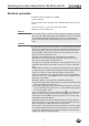
Operating Instructions Safety Switch CES-AR-C01-AH-SA Exclusion of liability and warranty In case of failure to comply with the conditions for correct use stated above, or if the safety instructions are not followed, or if any servicing is not performed as required, liability will be excluded and the warranty void. General safety instructions Safety switches fulfill personal protection functions. Incorrect installation or tampering can lead to fatal injuries to personnel.
Operating Instructions Safety Switch CES-AR-C01-AH-SA Function The device complies with the following safety requirements: ÌÌCategory 4, PLe according to EN ISO 13849-1 ÌÌRedundant design of the circuit in the unit with self-monitoring ÌÌThis means that the safety system still functions even if an internal component fails ÌÌThe switch state of the semiconductor outputs is continuously monitored internally ÌÌShort circuit detection at the safety outputs by pulse signals The following switch-on condition a
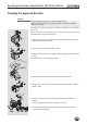
Operating Instructions Safety Switch CES-AR-C01-AH-SA Changing the approach direction Caution! Risk of damage to equipment as a result of trapped cables. ÌÌMake sure that the cables are not trapped or torn off when the approach direction is changed. The active face of the read head can be adjusted in 5 directions. It is marked by the red face. The plug connector can be realigned in 45° steps to change the direction of the cable outlet (when using elbow connectors). 1.
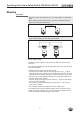
Operating Instructions Safety Switch CES-AR-C01-AH-SA Mounting Important! ÌÌFrom the assured switch-off distance Sar, the safety outputs are safely shut down. ÌÌWhen mounting several safety switches, observe the stipulated minimum distance to avoid mutual interference. min. 80mm ÌÌIf the actuator is installed flush, the switching distance changes as a function of the installation depth and the safety guard material.
Operating Instructions Safety Switch CES-AR-C01-AH-SA Electrical connection The following connection options are available: ÌÌSeparate operation ÌÌSeries connection with Y-distributors from EUCHNER (only with M12 plug connector) ÌÌSeries connection, e.g. with wiring in the control cabinet. ÌÌOperation on an AR evaluation unit Warning! In the event of a fault: Loss of the safety function due to incorrect connection. ÌÌTo ensure safety, both safety outputs (OA and OB) must always be evaluated.
Operating Instructions Safety Switch CES-AR-C01-AH-SA Caution! ÌÌIn order to avoid EMC interference, the physical environmental and operating conditions at the installation site of the device must comply with the requirements according to the standard EN 60204-1:2006, section 4.4.2 (EMC). ÌÌPlease pay attention to any interference fields in case of devices such as frequency converters or induction heating systems. Observe the EMC instructions in the manuals from the respective manufacturer.
Operating Instructions Safety Switch CES-AR-C01-AH-SA Requirements for connection cables Caution! Risk of damage to equipment or malfunctions as a result of incorrect connection cables. ÌÌUse connection components and connection cables from EUCHNER ÌÌOn the usage of other connection components, the requirements in the following table apply. EUCHNER provides no warranty for safe function in case of failure to comply with these requirements.
Operating Instructions Safety Switch CES-AR-C01-AH-SA Determining cable lengths using the example table Example: 6 switches are to be used in series. Cabling with a length of 40 m is routed from a safety relay in the control cabinet to the last switch (#6). Cables with a length of 20 m each are connected between the individual CES-AR safety switches. lmax = 140 m l2 = 5 x 20 m l1 = 40 m ln = 20 m un = min. 19,2 V Sicherheitsrelais iout = min.
Operating Instructions Safety Switch CES-AR-C01-AH-SA Connector assignment of safety switch CES-AR RST UB 0V IA IB OA OB OUT 8 2 7 6 7 8 6 1 5 4 1 3 4 5 Coding lug 2 3 View on the connection side of the safety switch Figure 2: Connector assignment of safety switch CES-AR Pin Designation Description 1 IB Enable input for channel 2 Wire color white 2 UB Power supply, DC 24 V brown 3 OA Safety output, channel 1 green 4 OB Safety output, channel 2 yellow 5 OUT/DIA Monitoring out
Operating Instructions Safety Switch CES-AR-C01-AH-SA Connection of a single CES-AR-C If a single CES-AR-C is used, connect the switch as shown in Figure 3. The OUT output can also be connected here to a control system as a monitoring output. The switch can be reset via the RST input. To do this, a voltage of 24 V is applied to the RST input for at least 3 seconds. The RST input must be connected to 0 V if it is not used. Important! The subsystem CES-AR complies with PL e in accordance with EN 13849-1.
Operating Instructions Safety Switch CES-AR-C01-AH-SA Warning! In the event of a fault: Loss of the safety function due to incorrect connection. ÌÌTo ensure safety, both safety outputs (OA and OB) must always be evaluated. Single-channel use of the safety outputs leads to a loss of the category in accordance with EN ISO 13849-1.
Operating Instructions Safety Switch CES-AR-C01-AH-SA Connection of several CES-AR-C in a switch chain Important! ÌÌAn AR switch chain may contain a maximum of 20 safety switches. ÌÌIn the estimation of the PL for the overall system, a maximum value of 100 years can be assumed for the MTTFd according to the limit value in EN ISO 13849-1:2008, section 4.5.2. This corresponds to a minimum value for the PFHd of 2.47x10⁻⁸/h.
Terminating plug 17 IB 6 IA Safety Inputs 1 8 Y-distributor 5 RST 2 UB 7 0V OA 4 OB CES Safety Outputs OUT 3 5 OUT 3 OA IB 6 IA Safety Inputs 1 8 RST 2 UB 7 0V Y-distributor OB CES Safety Outputs 4 IB 1 6 8 2 7 5 3 4 IA 4 4 OB 4 IB 0V 2 2 OA 3 3 0V 2 UB 1 IA RST 5 1 5 UB Read Head 1 Read Head RST Y-distributor IB IA RST UB 0V OUT OA OB UB Terminating plug IB 6 IA Safety Inputs 1 8 RST 2 UB 7 0V Y-distributor 5 3 OA 4 O
Operating Instructions Safety Switch CES-AR-C01-AH-SA Notes on operation with safe control systems Please observe the following requirements for connection to safe control systems: ÌÌUse a common power supply for the control system and the connected safety switches. ÌÌA clocked power supply must not be used for UB. Tap the supply voltage directly from the power supply unit. If the supply voltage is connected to a terminal of a safe control system, this output must provide sufficient electrical current.
Terminating plug 19 IB 6 IA 8 Safety Inputs 1 RST 2 UB 7 0V Y-distributor 3 OA 4 OB Safety Output OUT CES 5 IB 6 IA 8 RST Safety Inputs 1 2 UB 7 0V Y-distributor 5 3 OA 4 OB CES Safety Output OUT 1 IA RST 6 8 2 Safety Inputs IB UB 7 0V Y-distributor 5 OA OB LED1 UCM J 0V(UCM) CET 3 4 X2:3 X2:4 X2:5 X2:1 Safety Output OUT -X1 ET200 4 F-DO DO..M DO..
Operating Instructions Safety Switch CES-AR-C01-AH-SA Setup LED indicators LED STATE DIA Color State Significance illuminated Normal operation flashing - Teach-in operation or Power Up - Actuator in limit range (V. 1.1.
Operating Instructions Safety Switch CES-AR-C01-AH-SA Teach-in function for series connection It is recommended not to teach in the actuators in the series connection but to teach them in one by one instead. Teach-in in a series connection works analogously to individual operation in principle. All switches in the chain can be taught in at the same time. The prerequisite is that the switch chain functions without problems and the following steps are followed.
Operating Instructions Safety Switch CES-AR-C01-AH-SA Functional check After installation and any fault, the safety function must be fully checked. Proceed as follows: Warning! Danger of fatal injury as a result of faults in installation and functional check. ÌÌBefore carrying out the functional check, make sure that there are no persons in the danger area. ÌÌObserve the valid accident prevention regulations. 1. Switch on operating voltage. ÌÌThe safety switch carries out a self-test.
Operating Instructions Safety Switch CES-AR-C01-AH-SA System status table X off closed on closed on flashes quickly 2 Hz Normal operation, door closed, actuator in limit range Re-adjust door (V. 1.1.
Operating Instructions Safety Switch CES-AR-C01-AH-SA Technical data Note: If a product data sheet is included with the product, the information on the data sheet applies in case of discrepancies with the operating instructions. Technical data for safety switch CES-AR-C01-AH-SA Parameter Value min. Housing material typ. Unit max. PBT V0 GF30 Dimensions According to EN 60947-5-2 Weight 0.
Operating Instructions Safety Switch CES-AR-C01-AH-SA Typical system times The specified times are maximum values for AR switch chains with 20 devices. Individual devices have shorter system times. Ready delay: After switching on, the device carries out a self-test for 8 s. The system is ready for operation only after this time. Switch-on time of safety outputs: The max.
Operating Instructions Safety Switch CES-AR-C01-AH-SA Dimension drawings and connector assignments Safety switch CES-AR...
Operating Instructions Safety Switch CES-AR-C01-AH-SA Technical data for actuator CES-A-BBA Parameter Value min. Housing material Unit typ. max. Fortron, reinforced thermoplastic, fully encapsulated Dimensions Weight Ambient temperature - 25 42 x 25 x 12 mm 0.02 kg - Degree of protection acc.
Operating Instructions Safety Switch CES-AR-C01-AH-SA Switching distances Operating distance for center offset m = 0 (only in combination with CES-A-BBA actuator) Parameter Value Unit min. typ. max. - 18 - Switch-on distance 15 - - Switching hysteresis 1) 1 3 - Assured switch-off distance sar - - 45 Assured switch-on distance sao 1) mm 1) The values apply for surface installation of the actuator.
Operating Instructions Safety Switch CES-AR-C01-AH-SA Technical data for actuator CES-A-BPA Parameter Value min. Unit typ. Housing material max. PBT Dimensions 40 x 40 x 10 mm 0.025 kg Weight Ambient temperature - 25 - Degree of protection acc.
Operating Instructions Safety Switch CES-AR-C01-AH-SA Switching distances Operating distance for center offset m = 0 (only in conjunction with actuator CES-A-BPA on surface mounting) Parameter Value Unit min. typ. max. - 22 1) - Switch-on distance Assured switch-on distance sao 18 - - Switching hysteresis 1 2 - Assured switch-off distance sar - - 58 mm 1) On surface mounting on aluminum; in a non-metallic environment the typical switching distance increases to 30 mm.
Operating Instructions Safety Switch CES-AR-C01-AH-SA Technical data for actuator CES-A-BRN Parameter Value min. Housing material Unit typ. max. PPS Dimensions Weight Ambient temperature - 25 Degree of protection acc. to EN IEC 60529 80 x 40 x 15 mm 0.
Operating Instructions Safety Switch CES-AR-C01-AH-SA Switching distances Operating distance for center offset m = 0 (only in combination with actuator CES-A-BRN) Parameter Value Unit min. typ. max. - 27 - Switch-on distance 20 - - Switching hysteresis 1) - 3 - Assured switch-off distance sar - - 75 Assured switch-on distance sao 1) mm 1) The values apply for surface installation of the actuator on steel.
Operating Instructions Safety Switch CES-AR-C01-AH-SA Ordering information and accessories Designation CES-AR-C01-AH-SA Version Order No.
Operating Instructions Safety Switch CES-AR-C01-AH-SA Service If service support is required, please contact: EUCHNER GmbH + Co. KG Kohlhammerstraße 16 D-70771 Leinfelden-Echterdingen Service telephone: +49 711 7597-500 E-mail: info@euchner.de Internet: www.euchner.
Operating Instructions Safety Switch CES-AR-C01-AH-SA Declaration of conformity 35
Operating Instructions Safety Switch CES-AR-C01-AH-SA 36
Operating Instructions Safety Switch CES-AR-C01-AH-SA 37
Euchner GmbH + Co. KG Kohlhammerstraße 16 D-70771 Leinfelden-Echterdingen info@euchner.de www.euchner.de Edition: 098039-16-10/13 Title: Operating Instructions Safety Switch CES-AR-C01-AH-SA (translation of the original operating instructions) Copyright: © EUCHNER GmbH + Co. KG, 10/2013 Subject to technical modifications; no responsibility is accepted for the accuracy of this information. More than safety.