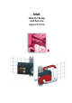
MGB Help for Setup and Service (up to V1.2.
MGB Help for Setup and Service Page 2/12 Subject to technical modifications 115387-01-04/12
MGB Help for Setup and Service Table of contents 1 Connection...................................................................................................................................................4 1.1 Connection of the buttons in the MGB...................................................................................................4 1.2 Control of the guard locking...................................................................................................................4 1.
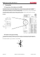
MGB Help for Setup and Service 1 Connection 1.1 Connection of the buttons in the MGB The terminal assignment of the switches (lights, buttons, emergency stop, etc.) in the cover of the MGB is not described in the system manual. These terminals can be found in the associated data sheet of the MGB included with every delivery. Please contact EUCHNER if the data sheet has been lost, and you will promptly be sent a data sheet. Alternatively, you can look in the MGB catalog.
MGB Help for Setup and Service 1.3 Parallel control of the guard locking The guard locking solenoids are supplied from voltage UA. The inputs UCM serve to control the solenoids; the current draw here is only approx. 3 mA. Several UCM inputs can be controlled in parallel if a common 0 V potential is present at OVM. 1.4 Operation on safety relay The MGB can be connected to most conventional safety relays.
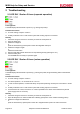
MGB Help for Setup and Service 2 Troubleshooting 2.1 LED DIA 1 flashes 2 times (separate operation) Fault symptom: The MGB displays the fault state “input error (e.g. missing test pulses)”. Possible fault causes: 24 V DC missing at inputs IA and/or IB A safety evaluation unit or a safe control system with clocking outputs is connected. Remedy: 1. Check the wiring and correct it if necessary or switch the clock pulses off 2. Open the safety door 3.
MGB Help for Setup and Service 4. Switch the voltage on again or release the reset button 5. Wait until LEDs DIA1 flash three times or stop flashing entirely (after approx. 8 s) 6. Close the safety doors The MGBs are now ready for operation again 2.3 LED DIA 1 flashes 3 times The device indicates that it is ready to teach in a new handle module. Observe the specifications for teaching in a handle module in the system manual for this purpose. 2.
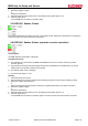
MGB Help for Setup and Service 2.5 LED DIA 1 flashes 6 times (AR version) Fault symptom: The MGB displays the fault state “signal sequence incorrect”. Possible fault causes: This state occurs if, with an MGB, the door was opened from the inside with the escape release or the guard locking solenoid was not opened before. If there is an internal fault (break) Remedy: 1. Open all safety doors on which the DIA LED is flashing (irrespective of the number of flashing pulses) 2.
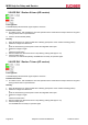
MGB Help for Setup and Service 2.7 Separate operation functions on the safety relay, but not series operation Fault symptom: The connection of a separate MGB operation to a safety relay functions, but the connection in series operation to a safety relay does not function despite correct wiring. The safety relay displays a fault or does not switch on.
MGB Help for Setup and Service 3 System status tables 3.
MGB Help for Setup and Service 3.
EUCHNER GmbH + Co. KG Kohlhammerstraße 16 D-70771 Leinfelden-Echterdingen Telephone +49 711 7597 – 500 (Support) Fax +49 711 753316 www.euchner.de . info@euchner.