
Owner's manual


Operating Instructions Safety Switch NM..WO/RB
Correct use
Safety switches of type series NM..WO (domed
plunger) and NM..RB (roller plunger) are used in control
systems that perform safety functions, e.g. for safety
guards or as position encoders.
The safety switches series NM comply with the
regulations of EN 60947-5-1, Annex K and comply
with the requirements of the employers’ liability
insurance associations for machines, installations and
personnel protection.
Before safety switches are used, a risk assessment
must be performed on the machine in accordance
with
EN ISO 13849-1, Safety of machinery. Safety related
parts of control systems. General principles for
design
EN ISO 14121, Safety of machinery. Risk
assessment. Principles
IEC 62061, Safety of machinery. Functional safety
of safety-related electrical, electronic and
programmable electronic control systems.
Correct use includes compliance with the relevant
requirements for installation and operation, particularly
EN ISO 13849-1, Safety of machinery. Safety related
parts of control systems. General principles for
design
EN 1088, Safety of machinery. Interlocking devices
associated with guards. Principles for design and
selection
EN 60204-1, Electrical equipment of machines
Important:
The user is responsible for the integration of the
device in a safe overall system. For this purpose
the overall system must be validated, e.g. in
accordance with EN ISO 13849-2.
If the simplified method according to section 6.3
EN ISO 13849-1:2008 is used for validation, the
Performance Level (PL) may be reduced if several
devices are connected one after the other.
If a product data sheet is included with the product,
the information on the data sheet applies in case of
discrepancies with the operating instructions.
Safety precautions
Safety switches fulfill a personal protection function.
Incorrect installation or tampering can lead to severe
injuries to personnel.
Safety components must not be bypassed
(bridging of contacts), turned away, removed or
otherwise rendered ineffective.
On this topic pay attention in particular to the
measures for reducing the possibility of bypassing
from EN 1088:1995+A2:2008, section 5.7.
Mounting, electrical connection and setup only
by authorized personnel.
Function
See travel diagram.
Mounting
Safety switches and trip dogs must not be used
as an end stop.
Safety switches and trip dogs must be arranged such
that they are adequately secured against movement.
To meet these requirements:
The fixings must be reliable and must also require
the use of a tool to undo them.
Mount the safety switch positively.
For safety-related applications (fixed positioning),
mount switch with M5x30 screws.
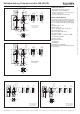
NM..RB
To ensure correct operation, the trip dogs must be fitted
as per the dimension
32
+0,5
(see Figure 6 and 7).
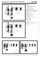
NM..WO
The maximum actuating dimension for the safety
switch is 28 mm (see Figure 4 and 5).
Protection against environmental influences
A lasting and correct safety function requires that the
actuating head must be protected against the
penetration of foreign bodies such as swarf, sand,
blasting shot, etc.
Cover the actuating head, the trip dog and the rating
plate during painting work!
Only use solvent-free cleaning agents to clean the
safety switch!
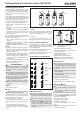
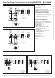
Switching elements and switching functions
Figure 2: Switching elements and switching functions
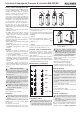
Electrical connection
When choosing the insulation material and wire
for the connections, pay attention to the over-
temperature in the housing (depending on the
operating conditions)!
For use and applications as per the requirements
of
, a class 2 power supply or a class 2
transformer according to UL1310 or UL1585
must be used. As an alternative, a low voltage
power supply according to UL508 table 32.1
can be used.
Fig. 3: Opening the safety switch
(Example NM..RB)
Break out the required entry opening.
Fit cable gland M16 x 1.5 with appropriate degree
of protection.
Conductor cross-section 0.34 mm
2
... 1.5 mm².
For terminal assignment see Figure 2.
Tighten the screws with a torque of 0.5 Nm.
Check that the cable entry is sealed.
Close the cover and screw in position.
Functional check
When the safety guard is open, the safety switch
must be actuated in any safety guard position
(overrun protection).
In safety circuits, check the safety function.
The machine must stop when the safety switch is
actuated.
The machine must not start when the safety switch
is actuated.
Mechanical function test
Check the actuating element for freedom of
movement.
Electrical function test
Actuate switch and check the switching function.
Inspection and service
If damage or wear is found, the complete switch
and actuator assembly must be replaced.
Replacement of individual parts or assemblies
is not permitted!
No servicing is required, but regular inspection of
the following is necessary to ensure trouble-free long-
term operation:
correct switching function
secure mounting of components
dirt and wear
sealing of cable entry
loose cable connections or plug connectors.
Note:The year of manufacture can be seen in the
bottom, right corner of the rating plate.
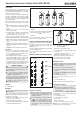
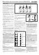
Figure 1: Changing the actuating direction (example NM..RB)
A
M=0,6Nm
ActuatedNot
actuated
21
13
21
31
11
21
31
31
21
13
21
22
14
22
32
12
22
32
32
22
14
22
21
31
21
13
31
21
11
21
31
21
13
22
32
22
14
32
22
12
22
32
22
14
NM01
NM12
NM03
NM11,
NM11..C2069
NM02
21
11
22
12
11
21
12
22
NM02..C2069