
User guide


Operating Instructions Safety Switches STP...
Correct Use
Safety switches series STP are electromagnetic inter-
lock devices with guard locking.
In combination with a separating safety guard and
the machine control, this safety component prevents
the safety guard from being opened while a dangerous
machine movement is being performed.
For the control system, this means that
f
starting commands which cause hazardous
situations must become active only when the safety
guard is in protective position and the guard locking
is in locked position.
The locked position of the guard locking must be
released only when the hazardous situation is no
longer present.
Before safety switches are used, a risk assessment
must be performed on the machine in accordance
with
f
EN ISO 13849-1, Safety of machinery. Safety related
parts of control systems. General principles for
design
f
EN ISO 14121, Safety of machinery. Risk
assessment. Principles
f
IEC 62061, Safety of machinery – Functional safety
of safety-related electrical, electronic and
programmable electronic control systems.
Correct use includes compliance with the relevant
requirements for installation and operation, particularly
f
EN ISO 13849-1, Safety of machinery. Safety related
parts of control systems. General principles for
design
f
EN 1088, Safety of machinery. Interlocking devices
associated with guards. Principles for design and
selection
f
EN 60204-1, electrical equipment of machines
Important:
f
The user is responsible for safe integration of the
device in a safe overall system. For this purpose
the overall system must be validated, e.g. in
accordance with EN ISO 13849-2.
f
If the simplified method according to section 6.3
EN ISO 13849-1:2008 is used for validation, the
Performance Level (PL) may be reduced if several
devices are connected one after the other.
f
If a product data sheet is included with the product,
the information on the data sheet applies in case of
discrepancies with the operating instructions.
Safety Precautions
Safety switches fulfill a personal protection function.
Incorrect installation or tampering can lead to severe
injuries to personnel.
Safety components must not be bypassed
(bridging of contacts), turned away, removed or
otherwise rendered ineffective.
On this topic pay attention in particular to the
measures for reducing the possibility of bypassing
according to EN 1088:1995.A2:2008, sec. 5.7.
The switching operation may only be triggered
by actuators specially provided for this purpose
which are permanently connected to the
protective guard.
Mounting, electrical connection and setup only
by authorized personnel.
Function
The safety switch permits the locking of movable
safety guards.
In the switch head there is a rotating cam that is
blocked/released by the guard locking pin. The guard
locking pin is moved on the insertion / removal of the
actuator and on the activation / deactivation of the
guard locking. During this process the switching
contacts are actuated.
If the cam is blocked, the actuator cannot be pulled
out of the switch head ¨ guard locking active.
Actuator Version
Actuator
S
for safety switches STP
without
insertion
funnel.
Actuator
L
for safety switches STP
with
insertion
funnel.
Versions STP1 and STP3
(Guard locking by spring force)
The guard locking pin is held in the locked position by
spring force and released by electromagnetic
actuation. The spring interlock guard locking functions
in accordance with the closed-circuit current principle.
The safety guard cannot be opened immediately in
the event of interruption of the solenoid power supply.
Versions STP2 and STP4
(Guard locking by solenoid force)
This type must be used only in special cases
after strict assessment of the accident risk!
The safety guard can be opened immediately in
the event of interruption of the solenoid power
supply!
The guard locking pin is held in the locked position by
electromagnetic force and released by spring force.
The guard locking operates in accordance with the
open-circuit current principle.
f Close safety guard and activate guard locking
The guard locking pin is released by insertion of the
actuator into the safety switch.
STP1 and STP3: The guard locking pin is moved to
locked position by spring force.
STP2 and STP4: The guard locking pin is moved to
locked position when the solenoid operating voltage
is applied.
The safety contacts are closed.
f Deactivating guard locking, opening safety guard
STP1: The guard locking pin releases the cam when
the solenoid operating voltage is applied.
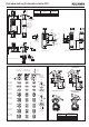
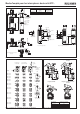
For switching function see Figure 3 column 2
Door
closed and not locked
The actuator can be removed.
STP2: The guard locking pin releases the cam when
the solenoid operating voltage is switched off.
For switching function see Figure 3 column 2
Door
closed and not locked
The actuator can be removed.
STP3 (with door monitoring contact): The guard
locking pin releases the cam when the solenoid
operating voltage is applied.
For switching function see Figure 3 column 2
Door
closed and not locked
The actuator can be removed.
On the removal of the actuator, the door monitoring
contact switches and signals that the safety guard is
open (see Figure 3 column 3,
Door open
).
STP4 (with door monitoring contact): The guard
locking pin releases the cam when the solenoid
operating voltage is switched off.
For switching function see Figure 3 column 2
Door
closed and not locked
The actuator can be removed.
On the removal of the actuator, the door monitoring
contact switches and signals that the safety guard is
open (see Figure 3 column 3,
Door open
).
Mechanical Release
In the event of malfunctions, the guard locking can be
deactivated using the mechanical release, irrespective
of the state of the solenoid (see Figure 2).
f
Unscrew locking screw.
f
Using a screwdriver, turn the mechanical release
by approx. 180° in the direction of the arrow.
The locking screw must be returned to its original
position and sealed after use (for example with sealing
lacquer).
Lock and Escape Release
On the actuation of the lock or the escape release,
the actuator must not be under tension.
The contacts 21-22 and 41-42 are opened and the
switch mechanically unlocked. The state of contacts
1x-1x and 3x-3x can vary.
Installation
Safety switches and actuators must not be used
as an end stop.
Mount the safety switch only in assembled
condition!
Caution! Risk of burns due to high surface
temperature at ambient temperatures above 40
°C! Protect switch against touching by personnel
or contact with inflammable material.
Assemble the safety switch so that
f
access to the switch is difficult for operating
personnel when the safety guard is open.
f
it is possible to operate the mechanical release and
check and replace the safety switch.
f
the escape release can be actuated from the hazard
area.
Fit an additional end stop for the movable part of the
safety guard.
f
Insert the actuator in the actuating head.
f
Mount the safety switch positively.
f
Permanently connect the actuator to the safety
guard so that it cannot be detached, e.g. using the
enclosed non-removable screws, rivets or welding.
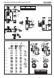
Changing the Actuating Direction
Figure 1: Changing the actuating direction
f
Remove the screws from the actuating head.
f
Set the required direction.
f
Tighten the screws with a torque of 0.6 Nm.
f
Cover the unused actuating slot with the enclosed
slot cover.
Protection against environmental influences
A lasting and correct safety function requires that the
actuating head must be protected against the
penetration of foreign bodies such as swarf, sand,
blasting shot, etc.
A
D
B
C