
User guide


Operating Instructions Safety Switches STP...
)x3( 5,1x0
2
M
30
<40>
h
4
4
1
5
,
5
3
5
,
1
4
30
4
091
22
16
<42>
0,5
v
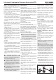
Figure 3: Switching elements and switching functions
E1
E2
E1
E2
v
h
E1
E2
Door closed Door closed Door open
and locked and not locked
Type
Pin assignment,
plug connector
SR6
STP1-528..
STP2-528..
SR11
Ordinal numbers
of switching
contacts
STP1-538..
STP2-538..
STP3-537..
STP4-537..
STP1-4131..
STP2-4131..
STP3-4131..
STP4-4131..
STP3-2131..
STP4-2131..
STP3-4121..
STP4-4121..
STP3-4141..
STP4-4141..
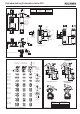
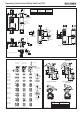
Figure 2: Dimension drawing STP... without insertion funnel and STP... with insertion funnel
L
h
35,5
45,5
30
4
194
9
16
4
0,5
0,5
v
19
19
4
With plug connector
SR6 or SR11
For M5 > 35 mm
ISO 1207 (DIN84)
ISO 4762 (DIN 912)
M = 1.5 Nm
Mechanical
release
M = 0.5 Nm
Locking screw
30
ca. 28
Actuating head with insertion funnel
M = 0.6 Nm
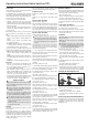
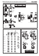
Figure 4: Min. door radii
Actuator type Door radius min. [mm]
Actuator S-G... 300
Actuator S-W... 300
HINGED ACTUATOR S-OU... 200
HINGED ACTUATOR S-LR... 200
Hinged actuator S-OU-LN for
insertion funnel
Hinged actuator S-LR-LN for
insertion funnel
16
30
R > 200
35,5
4
28,5 +5
20
R>200
Hinged actuator S-OU-SN
Hinged actuator S-LR-SN
24,5 +5
12
26
35,5
R >
20
200
R>
2
00
With mechanical key releaseWith escape release
Necessary minimum travel + permissible overtravel
Approach direction Actuator
S
Actuator
L
Standard Insertion funnel
Horizontal (h) 24,5 + 5 28,5 + 5
Vertical (v) 24,5 + 5 28,5 + 5
76,5
20,5
19
39
61,5
74,7
67,5
53
36
4
M4
∅14
20
31
locked
unlocked
Short axle
Long axle
locked
unlocked