
Instruction Manual


Operating Instructions Enabling Switch ZSM
Correct use
The EUCHNER enabling switch is a manually oper-
ated command switch, which allows work to be car-
ried out in the danger area of automated production
systems in the manual operating mode. This mode
must be secured with a lockable selector switch
according to EN 60204, part 1.
The enabling switch must be logically gated with the
machine control system in a manner that ensures
compliance with the requirements applicable to
safety circuits according to VDI 2854 and/or EN ISO
10218-1. Under the conditions specified therein, the
enabling signal may cancel the protective action of
moving safety guards. Authorized operating person-
nel may then enter the danger area:
f for setting up
f for observing work sequences
f for maintenance.
Important:
f The user is responsible for the integration of the
device in a safe overall system. For this purpose
the overall system must be validated, e.g. in ac-
cordance with EN ISO 13849-2.
f If the simplified method according to section 6.3
EN ISO 13849-1:2008 is used for validation, the
Performance Level (PL) may be reduced if several
devices are connected one after the other.
f The enabling switch user must assess and docu-
ment remaining risks.
f If a product data sheet is included with the product,
the information on the data sheet applies in case
of discrepancies with the operating instructions.
Incorrect use
The enabling signal must not be simulated by fixing
the switching contact in the enabling switch.
Attachments, such as key-operated rotary switches,
buttons, etc., are not allowed to be used for safety
tasks.
The stop button on enabling switches with plug
connector must not be used as an emergency stop
device according to IEC 60204-1.
It is only allowed to used a hard-wired electrome-
chanical emergency stop device for shutting down
in an emergency.
General
If 2-channel evaluation is used with monitor-
ing for same contact state, category 3 as per
EN ISO 13849-1 is attained.
Depending on the version, buttons, a key-operated
rotary switch and a stop button, etc., provide ad-
ditional functionality.
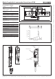
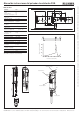
Function
Stage 1: Off function, pushbutton not pressed
Stage 2: Enabling function, pushbutton pressed to
center position (actuating point)
Stage 3: Off function, pushbutton pushed to end
stop
The enabling function is canceled by releasing the
pushbutton or pressing it beyond the actuating point.
The enabling function does not reactivate when
returning from stage 3 to stage 1.
Safety precautions
Enabling switches fulfill a personal protection func-
tion. Incorrect use or tampering can lead to severe
injuries to personnel.
All the safety and accident prevention regu-
lations for the specific application, e.g.
guidelines of the employers liability insurance
associations, safety requirements of the VDI
(EN ISO 10218-1, VDI 2854), EN 60204,
EN 12100, EN ISO 13849, EN 61062,
DIN VDE 0106 part 100, etc., must be ob-
served.
Electromechanical enabling switches/devices
are to be logically gated with the control system
in a manner that ensures compliance with the
requirements applicable to safety circuits ac-
cording to EN ISO 10218-1, DIN EN 60204-1,
EN ISO 13849-1, DIN EN ISO 11161 and
VDI 2854.
No commands for potentially hazardous condi-
tions are allowed to be initiated with enabling
switches alone.
The safety function of enabling switches must
not be bypassed (bridging of contacts), manipu-
lated or otherwise rendered ineffective.
The enabling switch must be protected against
attempts by the operator to bypass its function.
Enabling switches may be used only by au-
thorized persons who can recognize hazards
in time and who are able to take appropriate
action immediately.
Every person present in the danger area must
carry his/her own enabling switch on his/her
person.
Mounting, electrical connection and setup only
by authorized personnel.
Mounting
A suitable holder must be used for enabling
switches.
Electrical connection
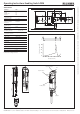
In safety circuits, both contacts on the enabling
switch must be evaluated separately (2-channel)
(Figure 1).
In the installation of a system, the cables and
wires used (except earth conductors) that can
be touched without opening or removing a
cover, or are laid on conductive parts external
to the device, must be either double insulated
or have reinforced insulation between core and
surface, or be surrounded by a metal sheath
of adequate current-carrying capacity in case
of a short between core and sheath.
For use and operation as per the require-
ments, a power supply with the feature “for use
in class 2 circuits” must be used.
Hazards due to crushing or cutting of the connec-
tion cable must be prevented by suitable measures:
f Protecting the cable by laying it appropriately, e.g.
in a protective sleeve.
f Monitoring short circuits using an evaluation unit.
f Using cable with individually screened cores. These
screens are to be connected to the machine or
plant earthing system. In this way cable short
circuits can be detected and the control system
shut-down immediately by the triggering of the
short circuit protection.
Setup
Check the enabling switch (enabling function at stage
2, and positively driven at stage 3) by performing
a functional check.
Depending on version: check the integrated func-
tions, such as stop button, key-operated rotary
switch, LEDs, etc.
Service and inspection
No servicing is required, but to ensure trouble-free
long-term operation, regular inspection of the electri-
cal and mechanical function is required.
In the event of functional faults or damage, the
enabling switch must be replaced. Repairs are
only to be made by the manufacturer!
Note: The year of manufacture can be seen in the
bottom, right corner of the rating plate.
Exclusion of liability under the following
circumstances
f incorrect use
f non-compliance with safety regulations
f electrical connection not performed by authorized
personnel
f non-implementation of functional checks.
EC declaration of conformity
The manufacturer named below herewith declares
that the product fulfills the provisions of the
directive(s) listed below and that the related stan-
dards have been applied.
EUCHNER GmbH + Co. KG
Kohlhammerstraße 16
70771 Leinfelden-Echterdingen, Germany
Directives and standards applied:
- Machinery directive 2006/42/EC
- EMC directive 2004/108/EC
- EN 60947-5-8:2006
Leinfelden, November 2010
Dipl.-Ing. Michael Euchner
Director
Duc Binh Nguyen
Authorized representative empowered to draw up
documentation
The signed EC declaration of conformity is included
with the product.