
Instruction Manual


Operating Instructions Enabling Switch ZSM
EUCHNER GmbH + Co. KG Kohlhammerstraße 16 D-70771 Leinfelden-Echterdingen Tel. +49 711 7597-0 Fax +49 711 753316 info@euchner.de www.euchner.com
Subject to technical modifications; no responsibility is accepted for the accuracy of this information. © EUCHNER GmbH + Co. KG 098540-05-08/11 (translation of the original operating instructions)
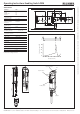
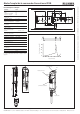
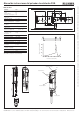
Figure 3: Dimension drawing, enabling switch ZSM and holder
5000 180
<79>
40
Plus/minus button
Key-operated switch
LED
Enabling switch
Stop button
DC 24 V
GND
-S1
1 2 3
Stufe
E1
0V
M
-
+
+24V
E2
E3
EUCH NER
ZS-M 09xxxx
A1
24VDC
A1
A2
S11
S10
ESM-BA2xx
S13
EUCHNER
Start
monitored
S21 S12
K1
+
S14
K2
+
13
14
23
24
Figure 1: Application example
Technical data
Parameter Value
Material
Housing
Enabling switch
Grip/seal
PA
CR
TPE
Degree of protection
according to IEC 529
IP54
Ambient temperature -5 ... + 60 °C
Degree of contamination
(external, according to
EN 60947-1)
3 (industrial)
Enabling switch
switching contacts
3 changeover contacts
Life 1 x 10
6
operating cycles
Utilization category
to IEC 947-5-1
(for enabling switch S4)
DC13 U
e
24V I
e
0.3A
U
e
24V I
e
1A
Short circuit protection
according to IEC 60269-1
1)
2 A gG
Weight Approx. 1.1 kg
Cable resistance ≥ 145 W / km
Conductor cross-section 0.14 mm
2
Cable length 5 m
Rated impulse
withstand voltage
U
imp
= 1.5 kV
Rated insulation voltage U
i
= 250 V
Rated short-circuit current 100 A
Reliability values according to EN ISO 13849-1
B
10d
1 x 10
5
1) In case of deviating cable lengths, the short circuit protection must
be dimensioned accordingly and checked.
0
2
4
6
10
20
30
40
0
a
b
1 3
2
Figure 2: Diagram of actuating force as a function of actuating travel
Actuating travel [mm]
Actuating force approx. [N]]