Control Surface Manual Document Revision: 1.1 Part Number: 840-08758-02 Release Date: September, 2003 Euphonix, Inc. 220 Portage Ave. Palo Alto, California 94306 Phone: 650-855-0400 Fax: 650-855-0410 Web: http://www.euphonix.com e-mail: info@euphonix.
In the interest of continued product development, Euphonix reserves the right to make improvements to this manual and the product it describes at any time, without notice or obligation. System 5, S5, PatchNet, eMix, EuCon, R1, Studio Hub, Audio Deck, Max Air, Reel Feel, Clear Displays, Track Panner, SnapShot Recall, DSC (Digital Studio Controller), HyperSurround, Total Automation and Mix View are trademarks of Euphonix, Inc. Manual design by Rob Wenig.
IMPORTANT SAFETY INSTRUCTIONS The lighting flash with arrowhead symbol within an equilateral triangle, is intended to alert the user to the presence of uninsulated “dangerous voltage” within the product’s enclosure that may be of sufficient magnitude to constitute a risk of electrical shock to persons. The exclamation point within an equilateral triangle, is intended to alert the user to the presence of important operating and maintenance (servicing) instructions in the literature accompanying the product.
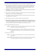
13) Unplug this apparatus during lightning storms or when unused for long periods of time. 14) Refer all servicing to qualified service personnel. Servicing is required when the apparatus has been damaged in any way, such as power-supply cord or plug is damaged, liquid has been spilled or objects have fallen into the apparatus, the apparatus has been exposed to rain or moisture, does not operate normally, or has been dropped.
Euphonix Max Air Control Surface Manual Table of Contents System Startup Sequence ..........................................................................................7 Description ................................................................................................................7 Overview.........................................................................................................7 Self Test Procedure ............................................................................
Euphonix Max Air Control Surface Manual List of Figures 1 Typical Console Layout ......................................................................................................7 2 CM404 Rear Panel ..............................................................................................................8 3 CM416 Rear Panel ..............................................................................................................8 4 Control surface self-test keys ........................
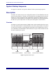
Euphonix Max Air Control Surface Manual System Startup Sequence See page 21 in the Max Air Operation Manual for the system startup sequence. Description The Max Air Console consists of a configurable number of Control Modules that comprise the Control Surface. The Max Air Control Surface is the digital control center for all Max Air system components and communicates with them via Ethernet network connections.
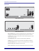
Euphonix Max Air Control Surface Manual Rear Panels INTERNAL EXTERNAL TALKBACK MIC TALKBACK MIC SERVICE AC IN 1 SERIAL 1 T 5.0 AH 250 V I I O ~100-240V AC 50-60 Hz 250 Watts O Caution: To prevent risk of fire, replace fuse with the same type and rating. SERIAL 2 TO KVM EXTENDER AC IN 2 MOUSE LAN CM404 KEYBOARD Figure 2 CM404 Rear Panel ~100-240V AC 50-60 Hz 250 Watts I Caution: To prevent risk of fire, replace fuse with the same type and rating.
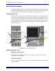
Euphonix Max Air Control Surface Manual Self Test Procedure The following pages describe the operation of standalone self-test software for the Max Air control modules. The self-test code is designed to be invoked in a module right after power-up and before the Single Board Computer (SBC) downloads code. Initiating Self Test Enter self-test by pressing the self-test enter keys shown below. This must be done before the SBC code download.
Euphonix Max Air Control Surface Manual LED Test LED loop This switch cycles through all the LED colors. Color Toggle These switches light all the LEDs of each color: green, red, yellow, orange All LEDS This turns all LEDs on. NOTE: To avoid overheating, the module should not be left with All LEDS on for more than 5 minutes. Fader Test All Fader Up All faders all the way up. All Fader Down All faders all the way down. Fader Echo Test All faders follow the one fader touched.
Euphonix Max Air Control Surface Manual Display Test Clear All Char Up Char Down Char E Char W Enumerate Memory Test ROM Test This test reads the ROM and computes and displays the checksum. The user/tester can match the checksum to a known good checksum (see below) to make sure ROM test is successful. CM404 Checksum - 6514 CM416 Checksum - D308 RAM Test This tests the upper unused portion of the CPU board RAM. The Pass display shows up when the test is done.
Euphonix Max Air Control Surface Manual Selecting and Adjusting the Onscreen Display The Touchscreen image controls are found on the panel behind the Touchscreen. If the image needs adjustment, access press the Menu button and follow the onscreen instructions.
Euphonix Max Air Control Surface Manual Touchscreen Alignment The Max Air Touchscreen can be calibrated using the Elo Touchscreen utility. Note that different users may have slightly different ways of touching the screen. If an operator finds they often miss onscreen objects, re-calibrate the touchscreen: 1. Select Control Panel from the Start menu. Figure 6 2. Double-touch Elo Touchscreen. Figure 7 The Elo popup appears.
Euphonix Max Air Control Surface Manual Figure 8 3. Touch Align and follow the onscreen instructions. When asked to touch the targets on the screen, best results are achieved by touching the targets naturally without thinking too much about it. This aligns the touchscreen to an individual’s hand-eye coordination.
Euphonix Max Air Control Surface Manual Changing the ID of a CM416 Module 1. Power cycle the module and then simultaneously press and hold the two lower knobs on the first strip before the module connects to the System PC (you have about 15 seconds).
Euphonix Max Air Control Surface Manual Technical Specifications Power Voltage Power Consumption Inrush Current Fuse Heat Dissipation 90–254 VAC (RMS), 50/60 Hz 2 x 50 W per module 1.0 A (US 117 V) 0.5 A (Europe 230 V) 1.
Euphonix Max Air Control Surface Manual 75.00° 16.25 CM416 BALANCE POINT CM404 BALANCE POINT Dimensions Dimensions in inches 16.13 15.625 8.39 6.78 3.06 2.06 1.20 5.85 4.39 0 9.83 11.42 20.83 22.42 28.50 29.58 0 Figure 10 Side Dimensions 0 .900 0 .902 KEEP CLEAR FOR VENTILATION 11.723 12.827 KEEP CLEAR FOR VENTILATION 1/4-20 THREADED INSERT 8 PLACES 23.400 24.300 Figure 11 CM416 Bottom Dimensions 17 .53 0 8.742 9.83 11.42 20.83 22.42 23.648 24.
Euphonix Max Air Control Surface Manual 0 .90 1.79 KEEP CLEAR FOR PROPER VENTILATION 1/4-20 THREADED INSERT 8 PLACES 19.46 .53 0 8.742 9.83 11.42 20.83 22.42 21.40 22.30 Figure 12 CM404 Bottom Dimensions 35.43 29.58 0.00 0.00 5.85 Figure 13 Max Air Top Dimensions 18 24.30 0.00 22.30 16.15 0.00 1.0 1.
Euphonix Max Air Control Surface Manual User Reference Internal Components Power Distribution Dual Power Connections Dual Power Supplies Single Board Computer KVM Extender Figure 14 CM404 Dual Power Connections Dual Power Supplies Power Distribution Single Board Computer Figure 15 CM416 19
Euphonix Max Air Control Surface Manual Fans The CM416 modules have low-noise internal fans and a thermal sensor between the displays on strips five and six. If a module gets too hot, the fans automatically turn on at a low or high speed depending on the temperature. The fans turn off automatically when the internal temperature returns to normal.