
Specifications


DF64 Digital Frame Manual Version 1.0 ©1999 Euphonix, Inc. Page 12
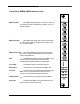
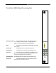
Front Panel, SP661 Signal Processing Card
DSP Activity LEDs These LEDs indicate the level of processing activity on
each of the SP661 Sharc processors. The lights glow more
brightly as each Sharc increases its processing activity.
Mute Indicates that all Audio signals from the SP661 to the TDM
bus are muted.
5V, 3V LEDs Indicate that 5 volt and 3 volt power are present.
Reset Button This button forces a manual reset of the SP661 card.
Error LED Indicates that an error condition has been detected on the
SP661 card. Is is normal for the Error LED to remain lit for 30
seconds or more after the DF64 is powered on
HotSwap Button Push this button prior to making a swap of the SP661 Card.
Ready LED Indicates that the SP661 card is disconnected from the
DF64 system bus and ready for removal.
DSP Activity
D
C
B
A
F
E
5V
Reset Error
HotSwap Ready
Mute
3V
SP-661
SIGNAL
PROCESSOR
Euphonix