CS3000 CS2000 MixView Software Supplement Version 3.
Table of Contents CS3000/2000 MixView Software Supplement Version 3.0 Revision 2 Worldwide Sales, Euphonix Inc. 11112 Ventura Blvd. #301, Studio City, CA 91604 Voice: (818) 766-1666 / Fax: (818) 766-3401 Corporate HQ, Euphonix Inc. 220 Portage Ave, Palo Alto, CA 94306-2242 Voice: (415) 855-0400 / Fax: (415) 855-0410 / Web Page: www.euphonix.
Table of Contents TABLE OF CONTENTS SECTION 1 : AUTOMATED EQ ............................... 1 - 1 Overview ............................................................................................... 1 - 1 EQ Object key ....................................................................................... 1 - 1 Writing EQ Moves ................................................................................ 1 - 1 All Parameter Punch .....................................................................
Table of Contents Cube Configuration ............................................................................ 4 - 20 System Configurations Cube Input Assignments .................................................. 4 - 20 “Standard” Cube Input Assignment Template ...................................................... 4 - 21 “Special” Cube Input Assignment Template ........................................................ 4 - 22 Direct Outputs ................................................................
Table of Contents SECTION 7 : CHANNEL FUNCTION ENHANCEMENTS ... 7 - 47 Overview ............................................................................................. 7 - 47 Aux Modes .......................................................................................... 7 - 47 Exercise 1 ............................................................................................ 7 - 47 Mono Independent Mode ......................................................................................
Table of Contents SECTION 10 : MX464 ...................................... 10 - 69 Master Section External Input Selection .................................... 10 - 69 Pulsed GPI Switching...................................................................... 10 - 70 System-wide GPI Relay and Speaker Mutes .............................. 10 - 70 Assigning Custom GPI Names ............................................................................. 10 - 72 DSC Mon Cnfg Page 3 Clear ........................
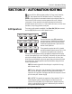
Section 1: Automation EQ SECTION 1 : AUTOMATED EQ M Overview ixView v3.0 provides dynamic automation of EQ. All EQ parameters can be individually punched-in via the DSC rotary controls or simultaneously all punched-in via the channel EQ•Dyn attention key. EQ object key The EQ is considered an object like the Fader, On and Pan keys, etc. In v3.0 software, the D object key becomes the EQ object key (EQ/D) similar to the Fader/A, Pan/B and On/C keys.
Section 1: Automation EQ By using the Pass Control screen, the A, B, C and D rows are assignable, via menu selection, to display several EQ automation parameters and their automation moves. The display is similar in style to auxes, pans and faders. They can also show combinations of EQ and Aux moves if desired. Additional EQ Automation Features Press [Pass Ctrl] to view the Pass Control screen.
Section 2: Automation Editing SECTION 2 : AUTOMATION EDITING T he new Off-Line Editing system provides Cut, Copy, Insert, Overwrite, Fill, Gap, Repeat, Bounce & Distribute functions. These allow the operator to piece together the automation data of various objects (Fader, On, Pan and now EQ) from current or previous passes within a mix, forming a custom pass. In some operations, automation data may be inserted into dissimilar objects of the console, i.e., from a fader into an aux, etc.
Section 2: Automation Editing OVR (OVERWRITE) : This operation accompanies a Copy operation. Existing data is overwritten (no time is inserted) by the contents of the copy buffer beginning at the Start point. During an Overwrite operation, the End point is ignored and the Length of the Overwrite is equal to the size of the copy buffer contents. Automation data will Overwrite only into the block it was copied from. You can not for example Overwrite data from lower fader 12 into upper$OËâ›r 23.
Section 2: Automation Editing Edit Template Press [F3] to view the template screen. Edit template color legend Here you will select the objects to be included in the edit operation by pressing the appropriate DSC Object key (Fader, Pan ,On etc.) and then pressing the appropriate block attention key. Selected desk objects turn green for individual objects, yellow for group master objects and blue when the selected object is both a group master and underlying individual object.
Section 2: Automation Editing Using Cue/Locate points From the T/C menu press [F4] (Cue). Use the Numeric keypad, the [+]/[-] keys or the SpinKnob to select a cue number from the cue list and press [Enter]. Again, use [F1] to toggle between “Start” and “End”. For detailed information on the Locate/Cue system refer to the CS3000/2000 Operation Manual. On-The-Fly While in the T/C menu, toggle to “Start” and play the T/C source.
Section 3: Automation Utilities SECTION 3 : AUTOMATION UTILITIES Punch Menu T he Punch menu allows you to accomplish three useful automation tasks: 1. Establish an automation “Punch Group” to allow a collection of objects to be punched in with a single DSC keystroke. 2. Disable Write In, Write Out and Write Through at the end of each automation pass via a menu preference. 3. Allow the punch out “Filter” to follow the Object select keys via a menu preference.
Section 3: Automation Utilities template is visible, the [All Lower], [All Upper] and [All Aux] keys operate to arm/disarm their respective Mix Controller object blocks. When the template is not visible on-screen, these keys punch-in those object blocks.
Section 3: Automation Utilities Pass 8 with good fade in: Pass 5 with good scene change: Pass 12 with good fade out: Result of pass join: The above diagram graphically shows a join operation for a single fader. Once the Join operation is complete, you can play the mix with the new “joined” pass. If you don’t like it , you can go back into your list and edit the “FROM” and “TO” pass numbers, or change transition time by editing each transition’s “AT” timecode number and then re-execute.
Section 3: Automation Utilities Viewing the Pass Join List Stop timecode and view the Pass Join menu and list. From the top-level Pass Control menu, press [F4] (down arrows), [F4] (Util) and then [F2] (Join): Pass0 Undo? Redo? F1 F2 F3 Clr? Pack? F1 F2 View Join Group Trim F4 F1 F2 F3 F4 Edit Util Join? Edit Tplt ON F3 F4 F1 F2 F3 F4 This is the Pass Join menu. On the screen you will see the Pass Join list.
Section 3: Automation Utilities Once the list is complete, the next step is to select the objects that will be included in a Join operation. This can include all objects on the console or only a select few. Objects are selected in the Pass Join template. From the Pass Join menu, press [F3] to see the template on the screen display: Join Template Join? Edit Tplt ON F1 F2 F3 F4 Join? Edit View F1 F2 F3 ON F4 F3 toggles between the Template and the Join list.
Section 3: Automation Utilities will select all Aux A blocks. The operation should now be clear. A shortcut for selecting all objects is pressing the [*ST] key. You will see all objects turn green in the template. Press [Clr] to clear the template. Execute the Join Once the desired objects are included in the template, press [F1] to execute the join. A new pass is created in the pass tree branching from the first “FROM” pass in the join list.
Section 3: Automation Utilities By default the Base Pass will be the first “FROM” pass in the list. It was your starting pass and where the join pass will branch from. The example outlined in the section introduction was pretty basic. You can get quite creative with the Join operation however. Expanding on the example , imagine applying this join sequence to 4 faders only, and allow all other automated objects to follow a separate Base Pass throughout the mix.
Section 3: Automation Utilities MBR mode can be applied to both moving and non-motorized fader systems, and in absolute as well as trim modes. Normally, in order to automate a fader, you would press the [Mix On] key to activate the mix system, select the [Fdr] object key, play the time code source (see Pass Rec light) and press any fader’s punch (attention) key to immediately begin writing automation data.
Section 3: Automation Utilities SIDE NOTE: Remember that MBR mode is only relevant if the fader contains previously recorded automation data. Without automation, the first press of the fader's punch (attention) key will drop that fader immediately into automation record. Aborting MBR Mode Non-motorized fader The fader’s null LEDs will begin blinking at a fast rate. This signifies that fader is now in MBR mode.
Section 3: Automation Utilities This page intentionally left blank 3 - 16 Euphonix CS3000/2000 MixView 3.
Section 4: The Audio Cube SECTION 4 : THE AUDIO CUBE A n important option available for the Euphonix console is the Audio Cube System. The Audio Cube is a digitally controlled level/routing matrix which allows the addition of multi-format buses to any Euphonix console; multitrack buses, auxiliary send buses, and film panning buses can be made available from any fader.
Section 4: The Audio Cube Once the Hyper-Surround panners are configured, the are accessed by pressing the DSC [Pan Assign] key. While in the Pan menu and screen, calling attention to any fader block will access the panners available to that fader. Hyper-Surround Panning DSC Screen Display Active panner meters & position Bus Master level display for 5.
Section 4: The Audio Cube The Audio Cube System is comprised of four (4) major components: the chassis, the power supply, the Quad Bus Cards (QBCs) and the interconnections which include patchbays and cabling.
Section 4: The Audio Cube Interconnections Supplied cabling connects the DIRs of the channel patchbays to the Cube inputs and the Cube outputs to a dedicated patchbay. The output patchbay provides connections for the Cube’s bus insert sends/ returns and bus outputs. A single 96 point patchbay will accommodate up to 24 Cube output buses. If a system is equipped with more that 24 output buses, two tie-line patchbays are supplied.
Section 4: The Audio Cube To view the Cube Input Assignment Templates, press the [Bus Master] DSC key: View the Template Bus 1 -> F1 OFF F2 F3 F4 I/O Bus Assign F1 F2 F3 Standard Press [F1] (Standard): F1 F4 Special F2 F3 F4 Sys: F 56 [Yes] F1 F2 F3 F4 Use [F2] to select the system type and [F3] to select the system size. Then press [F4] to confirm.
Section 4: The Audio Cube M-40 Cube Input Assignment Template Above is a 40 faders, M-40 system. The Cube has 48 inputs leaving 8 Cube inputs for future console expansion. F-32 Cube Input Assignment Template Above is a 32 fader F-32 film system. The Cube inputs are “short loaded” to 32 in this system, instead of the usual 48. This is because typically, F systems send only lower fader signals to the cube via the consoles DIR 1 output.
Section 4: The Audio Cube Lowers Only - This mode assigns Cube inputs to the Mix Controller’s lower faders only. If there are fewer lower faders than Cube inputs, the remaining Cube inputs are not assigned. Uppers Only - This mode assigns Cube inputs to the Mix Controller’s upper faders only. If there are fewer upper faders than Cube inputs, the remaining Cube inputs are not assigned. Wrapped [n] - Cube inputs are assigned to lower faders up to the channel number in brackets.
Section 4: The Audio Cube [Automatic] - Assures that all lower faders have Cube inputs. This mode is similar to L/U [n] except that it automatically enters the total number lower faders in the console as [n]. Executing [Automatic] on the console in the above example would look like this: Direct Outputs The next stage of system configuration is setting the channel DIR assignments. Every Cube input must receive a post fader feed from the console.
Section 4: The Audio Cube Selectable on-screen metering is available for every Cube bus. Meters can be switched to read the Bus Out (pre-master control & insert send), Master In (insert return), and Master Out. To select the Meter Source menu: Cube Metering I/O Bus Assign F1 F2 F3 Meters F4 Diags F1 F2 Meters-> Bus Min Mout F1 F2 F3 F4 F3 F4 Press [F2], [F3] or [F4] to select a metering point. The meters appear in the Aux, Aux Bus Master and Pan Bus Master screens next to each knob.
Section 4: The Audio Cube Operational Configuration Operational configurations are often done on a session by session basis. It is easy to reenter these menus and re-configure aspects of the system the needs demand. Define Bus Types The first step in Operational Configuration is to define the bus types as to their function. Buses are defined as “Aux” for use as Cube aux sends and “Pan” for use in building Hyper Surround™ Panners. Press the DSC [Bus Master] key to view the top level Cube Bus Master menu.
Section 4: The Audio Cube For this exercise, we will start with unconfigured Cube Buses. If the Bus Configure page is not clear, press the DSC [Clr] key and then [F3] (Yes) to the “Remove All?” prompt. Exercise 1 Defining Buses We will configure the system to have 6 Aux and 6 Pan type buses. While in the Bus Configuration menu and screen, press [F1] to select the type of bus you need. The choices are: AUX, PAN, or NONE. You will see “none” in brackets next to the bus type.
Section 4: The Audio Cube Cube Aux Masters Press the DSC Aux then Bus Master keys (both are lit). You will see the 6 Aux Bus Master controls on screen in the lower left. The Cube aux system works similarly to the console aux system in that there are fader aux sends to each bus and a aux master bus level. On screen you see the Aux Master controls, each with a dB readout a meter and a name block. Screen controls are mapped to the DSC rotary knobs.
Section 4: The Audio Cube On the Aux Bus Master screen you'll see a Bus Kill switch in the lower left of the control set. This is an “all mute”. It mutes all aux masters. You then unmute them individually from the bus mute key below each control. Buss Kill 6 Cube buses are configured as aux sends. We've explored the aux master controls. Now we will look at the Cube aux sends from individual faders.
Section 4: The Audio Cube Aux Copy Copy is done from the top level Cube Aux menu. Select the Cube aux send set you wish to copy then press F1. Press fader attention keys to copy all aux level and status to subsequent faders. Pan Bus Masters The last subject of this section covers the pan bus master controls. Press Pan Assign and Bus Master DSC keys.
Section 5: Hyper-Surround SECTION 5 : HYPER-SURROUND Overview M ixView 3.0 introduces the new Hyper-Surround Multi-Format surround panning interface providing more comprehensive control over your surround mix. Euphonix Hyper-Surround uses a system of virtual “panners” to distribute the signal from the consoles Hyper-Surround equipped faders to stem buses. A stem is defined as a group of buses or tracks of a recorder, organized to accommodate a specific monitoring environment from mono to 7.1 and beyond.
Section 5: Hyper-Surround panner that is just the Sl-Sr (surrounds) sending to buses 4 and 5. All of these formats and more are possible simultaneously with Hyper-Surround. You will need 11 buses defined as pan buses in your Cube to complete all three exercises. To quickly determine the number of pan buses available, press the DSC [Pan Assign] and then [Bus Master] keys to view the Pan Bus Master screen. The number of red bus master pots displayed on the screen indicates the number of Pan buses available.
Section 5: Hyper-Surround The panner screen appears in the right half of the DSC screen display. Assuming no panners have been built, all panners are blank. Selecting a Format Selecting a Channel The blue cursor is in the first block of the first panner. Press [F2] to begin selecting the panner format. While viewing the SmartDisplay menu, use the SpinKnob or [+]/[-] keys to scroll through the available formats until you see “5.1”: P1-> 5.1:L F1 F2 B–– F3 F4 Notice that “5.
Section 5: Hyper-Surround Naming the Panner While still in the panner setup menu, panner names can be entered from the QWERTY keyboard. The panner with the blue highlight in the vertical name column on the left side of the panner blocks is the one selected for naming. Press [F1] on the QWERTY keyboard, type the name and press [Enter]. The name will appear in the 8 character display next to the corresponding left column DSC key and in the left hand panner screen.
Section 5: Hyper-Surround Front Focus- Focus control is unique to the Euphonix Hyper-Surround system. It is similar in function to divergence. The major differentiating factors are that the Focus control does not render the L-C-R pan control ineffective, and that it requires three or more buses in order to function.
Section 5: Hyper-Surround The Assignable Keys When in Pan Assign mode, the two columns of DSC assignable keys become integral to the Hyper-Surround system. The left column keys are the Panner Keys, used for assigning elements (faders) to panners. The panner name will appear in the 8 character display next to each left column key. Once panners are set up, you simply attention a fader then turn on the desired panner by pressing a panner key.
Section 5: Hyper-Surround assigned or unassigned. This is useful after all assignments are made because panner assignment is locked out, essentially “safing” all assignments. LCRS Assign keys - These keys allow limited quick, hard pan assignments even while in pan mode. This is similar to the bus mode except that the panner controls are still active. Press L and see the front pan control move to the extreme left and the dot locate hard left on the grid. In a 5.
Section 5: Hyper-Surround Notice that in both the Full 5.1 and the LCR 5.1, the bus indication on the panner setup display changed from black to yellow background. Yellow in the bus indication window tells you that the bus is shared by another panner. In this case panner 1 and panner 2 share buses 1, 2 and 3. A panner’s ability to have common buses is a powerful feature of HyperSurround. The system will not permit a fader to be assigned to two panners simultaneously if the panners have common buses.
Section 5: Hyper-Surround Again select the 5.1 format. Press [F3] moving the flag to the channel indication above F3. Change the channel to Sl (SpinKnob). Press [F4] () to assign a bus number. Change the bus number to 4 (same as panner 1). Press the DSC [right arrow] key and then [F2]. Notice the automatic assignment of 5.1 Sr into the second block. Press [F4] and change the bus to 5. Press [Esc] to use the panner. With the [Pan Assign] key lit you are now ready to use the three panners you've constructed.
Section 5: Hyper-Surround Custom Formats Several additional “custom” formats are included. These custom formats were originally created for theatre and theme attraction based mix environments. However many have been found useful by film mixers wishing to push the envelope. You decide…: 4x1 through 9x1 - Front pan control will pan through each bus consecutively. Front Focus and divergence function as defined. The Cube bus outputs can be patched into a recorder input to create unique pan vectors as desired.
Section 6: Moving Faders SECTION 6 : MOVING FADERS E uphonix CS3000 & 2000 series consoles are designed to accept Euphonix Moving Fader automation hardware and software. Each optional moving fader I/O controller module provides four premium quality, touch-sensitive, motorized faders in the lower fader positions as well as four premium quality, non-motorized faders in the upper positions.
Section 6: Moving Faders Moving Fader Options Moving Fader software provides preferences which allow the user to customize the way the system responds and performs. There are three (3) menus containing four (4) moving fader preferences to review. The menus are: 1. Moving Fader menu 2. Touch/Release menu 3. Slaves menu The preferences are: 1. 2. 3. 4.
Touch ON/OFF Section 6: Moving Faders The next option we will look at is Touch:On/OFF. This preference is located in the Touch/Release menu. Press [F3] to get the Touch/Release menu. Moving Faders Menu Motors:ON F1 Touch/Release Menu F2 Touch:ON F1 F2 Touch Slvs F3 F4 Release:ON F3 F4 SIDE NOTE: Press the DSC [ Punch] key to quickly access the settings for Touch & Release from the top-level Punch menu.
Section 6: Moving Faders SIDE NOTE: If Motors are set OFF, Touch and Release are also turned OFF. However, you can then set Touch ON again, allowing you to have Motors:OFF with Touch:ON for punch-in purposes. With Release OFF the fader will remain in automation write mode (punched-in) after you remove your finger from the cap. The fader is punched-out manually using the fader punch (attention) key or by interrupting time code. The console default is Release:ON.
Section 6: Moving Faders Auto Dynamic™. After an initial punch-in has written, automation data for a fader, all subsequent punch-ins on that fader are done by touch-punch unless the Touch preference is set OFF in the SmartDisplay menu. (See previous section of this supplement) It is also possible for the CS3000/2000 automation system to emulate these other systems as well. You will first want to get a basic manual mix on your console.
Section 6: Moving Faders This page intentionally left blank 6 - 46 Euphonix CS3000/2000 MixView 3.
Section 7: Channel Function Enhancements SECTION 7 : CHANNEL FUNCTION ENHANCEMENTS Overview T here are four (4) aux send controls on the CS3000/2000 Mix Controller labelled A, B, C and D and divided into two console aux blocks (A/B) & (C/D). Each of the controls is capable of independent addressable operation and can be sourced from any of the console’s six (6) channel inputs and assigned to any of the eight (8) aux buses.
Section 7: Channel Function Enhancements SIDE NOTE: Since aux sends A/B and C/D share their respective aux blocks, the DSC [left arrow] and [right arrow] keys are used to direct attention between them. M1 M2 DIR L1 L2 ST1 Press the DSC [L4] key to directly assign the aux source routing: Aux Source Menu L3 L4 Left and right DSC arrow keys 16A-> F1 ST2 L4<-p. .
Section 7: Channel Function Enhancements Repeat the previous steps for aux sends C and D. Once completed, you can verify routing by feeding a test tone to L4 and trying the aux sends. Be sure the aux bus master controls are turned up and unmuted. This concludes Exercise 1.
Section 7: Channel Function Enhancements You can verify source tracking with the following steps: 1. Press channel 16’s fader block attention key. 2. Remove the L4 source selection by pressing the [L4] source select key and confirm that L4 has also been removed as an aux send source. 3. As you select or deselect other fader sources (M1, L3, etc.), notice that the Aux source indicator lights track the Lower fader source display.
Section 7: Channel Function Enhancements Level/Pan Linked Modes L/P mode links the A/B or C/D aux block pairs M1 M2 ... L4 Odd Even into mono in, stereo out level/pan linked (mono in/stereo out) configurations or stereo in, stereo out level/ (stereo in/stereo out) balance linked configurations. Odd Even Odd Even For the benefit of existing users who have upgraded to MixView 3.
Section 7: Channel Function Enhancements Press the [*ST] key followed by [F3] (Yes) to change to stereo linked mode: AB Stereo Aux ? Yes F1 16AB-> F1 * [No] F2 F3 F4 Stereo Bal Ind? F2 F3 F4 Press the [*ST] key again to select MonoPan mode: M1 M2 DIR L1 L2 ST1 L3 L4 ST2 16AB-> MnPan Ctr Ind? F1 F2 F3 F4 Press the DSC [L4] key to directly assign the aux source routing: 16AB-> F1 L4<-p. .
Mono Pan Center Locked Mode Section 7: Channel Function Enhancements There are some additional mono-in variations which bear mentioning at this time. From the Aux Status menu, press [F3] to lock the pan control signal at the center: 16AB-> MnPan Ctr Ind? F1 F2 F3 F4 Mono mode An additional mode is accessible from this Level/Pan Mode menu.
Section 7: Channel Function Enhancements Press the DSC [L3] & [L4] key to directly assign the aux source routing: M1 M2 DIR L1 L2 ST1 L3 L4 ST2 16AB-> F1 L3 L4<-p. . F2 F3 F4 Press the DSC keypad [1] & [2] keys to directly assign the aux send to aux bus 1 & 2: 7 8 9 16AB-> BUS 1 2 4 5 6 F1 F2 F3 1 2 3 F4 As with the mono in/stereo out modes, the aux A (C) pot becomes the pan control and the aux B (D) pot becomes the level control. The aux send is now ready for use.
Stereo Individual mode Stereo Reverse Modes Copying an Aux Setup Section 7: Channel Function Enhancements To get separate left and right controls instead of a level/balance combination, press [F3] again to select Stereo Individual mode: 16AB-> Stereo Ind Ind? F1 F2 F3 F4 Additionally, stereo Balance, Center Locked and Individual modes are available with reversed input signal pairs.
Section 7: Channel Function Enhancements You can set the meter modes globally for all channel I/O meters or for indiMeter Modes vidual channels. To set the meter mode globally, press the DSC [Mtrs] key, then [F2] (I/O): SIDE NOTE: Assigning meter modes globally by using the DSC Mtrs key, always overrides and changes any individual channel meter assignments.
Section 7: Channel Function Enhancements The following list details available selections: LEFT METER: Aud: M1, L1*, L3, CMB*, MT, LFL, UFL, OFF Lvl: UF, UP, A, C, M1, OFF, LF, LP, B, D, M2 SIDE NOTE: Any combination of sources you cannot monitor directly can be monitored using the Combiner. RIGHT METER: Aud: M2, L2*, L4, MT*, CMB*, LFR, UFR, OFF Lvl: LF, LP, B, D, M2, OFF, UF, UP, A, C, M1 An asterisk (*) indicates that choice is available only for F Rev channel hardware.
Section 7: Channel Function Enhancements Now press the [+Bus] or [F3] keys to assign the MT bus to Out3. M1 M2 L1 L2 L3 L4 60 33 U B 60 33 F M1 2 M1 2 L1 2 L1 2 L3 4 L3 4 Out 1 Out 2 1CH->OUT3 F1 F2 MT F3 F4 If M1 had been previously set as the Out3 source, MT replaces it. You may also use the DSC Source Assign keys to assign additional sources to Out3.
Section 8: MIDI Remote Control SECTION 8 : MIDI REMOTE CONTROL T he CS3000/2000 contains many MIDI communication capabilities. These features include control and automation of MIDI outboard FX equipment, external control of the console from MIDI sequencers in both studio and live applications and SnapShot linking between consoles in our multi-operator film systems. Overview Additionally, several objects on the Mix Controller are now able to send and receive MIDI continuous control data.
Section 8: MIDI Remote Control The double-ended arrow in the MIDI presets menu, designates which parameter is currently adjustable. Parameters are adjusted using the SpinKnob, [+]/ [-] or Numeric keys (See side note below for details). Assigning MIDI Presets Press [F1] (MP01) and select a MIDI preset from 1 to 50: MP01 01 Ch1 ––– RCL F1 F2 F3 F4 Each preset can transmit sixteen (16) different program changes.
Section 8: MIDI Remote Control Assigning MIDI channel Descriptive names may be assigned to any MIDI channels by pressing [F1] on the QWERTY keyboard. The Assignable key display shows up to eight characNames ters while the SmartDisplay menu shows the name’s first three characters: Reverb 1 PRG 31 9 2 — — — 10 Ch 2 MP01 01:Rev F1 F2 31 RCL F3 F4 After entering/modifying a MIDI preset, you can choose to send all of its assigned program changes at once or each program change individually.
Section 8: MIDI Remote Control channel and program change), press the [*ST] key to link that preset to the selected SnapShot. Before establishing the link, a confirmation menu is displayed: MP37 linked to SS03 F1 F2 F3 F4 The double-ended arrow indicates that you can change to another SnapShot at this time if desired. To complete the link, press the [Enter] key.
SIDE NOTE: Section 8: MIDI Remote Control the transmit and receive MIDI channels respectively. The double-ended arrow designates whether the transmit or receive MIDI channels (1-16) may be changed. Different situations may require more control versatility. All that is transmitted (or received) are MIDI program changes on standard MIDI channels, so rerouting is possible by altering the default setup.
Section 8: MIDI Remote Control MIDI Chan: Designates what MIDI channel is to be used for the communication between the console and the external device. (Na/Nc) SIDE NOTE: Adjustment methods: S= SpinKnob & [+]/[-] keys move cursor vertically within column. F= [F4] toggles field value. Na= (Arrow)* SpinKnob, [+]/[-] keys & Numeric keypad set numeric field value. Nc= (Colon)* SpinKnob & [+]/[-] keys move cursor vertically within column.
Remote Control of Console Objects by External Equipment (IN) Section 8: MIDI Remote Control You can also continuously control console objects using external MIDI equipment via port 3 of the console’s MIDI interface box. From the top level MIDI menu, press [F1] to display the MIDI In screen: Unlike the MIDI Out feature, there are many more console object choices capable of being controlled by external signals. (The above screen shows only a portion of the entire list of controllable console objects.
Section 8: MIDI Remote Control This page intentionally left blank 8 - 66 Euphonix CS3000/2000 MixView 3.
Section 9: Fader Links SECTION 9 : FADER LINKS™ F ader Linking allows any Group Master Fader or mute to internally control any automatable parameter within the console. Controllable objects include everything on the MIDI Remote Control, “able to receive control data” list. This feature provides a preliminary Cube automation solution. Full Cube automation will come in the version following 3.0. Overview *No release date/number has been assigned to the next version as of yet.
Section 9: Fader Links The DSC [left arrow] and [right arrow] keys are used to navigate horizontally from column to column. Column values can be changed or entered using the SpinKnob, [+]/[-] keys or directly with the DSC Numeric keys. Pressing [F3] and [F4] sequences the controller assignments. Press the [right arrow] key once to select the Controller Chan column: Cnsl Chan F1 F2 1 F3 F4 The double-ended arrow in the SmartDisplay means that the SpinKnob can be used to change the Chan value.
Section 10: MX464 SECTION 10 : MX464 Master Section External Input Selection I n previous versions of software, it was necessary to manually set the Master Control Ext input selections once all assignments had been made in the DSC Assignable keys display . MixV iew v3.0 now automatically sets these monitor input sources depending on the options selected in the Mon Cnfg/Pg 4 Assignable keys display .
Section 10: MX464 To sum Ext 1 with all other Master Monitor settings, set the Mon A, B or C parameter to “ ∑”. To add Ext 1 and cancel all cur or C parameter to “i”. rent Master Monitor settings, set the Mon A, B To shut of f all Master Monitor settings, set the Mon A, B or C parameter to “k”. Mon A ∑ 4 Mon B 5 Mon C 6 Selected parameters appear to the right of the alpha display .
Section 10: MX464 Column names and their functions are as follows: • • • • RELAY: The r elay number being addr essed. INIT: The state to which a r elay is set when initialized or r eset. TRIGGER: The fader object contr olling the r elay . STATE: The “active” position of the r elay when trigger ed by the upwar d movement of the fader object. • COMMENT: The name of the r elay assigned by either the console or the user.
Section 10: MX464 Pr ess [ F2] to sequence thr ough the available INIT and ST settings and observe the DSC screen: ATE parameter It is advisable to set the INIT field first and then set the ST ATE field as the for mer always r esets the latter to a default when subsequently accessed again. Press [ F4] if you wish to modify the ST ATE column. The last two screens show the pulsed relay icons and settings.
Section 11: Miscellaneous SECTION 11 : MISCELLANEOUS Overview I Locate Menu System The Locate menu is accessed by pressing the DSC Transport Control [Loc] key. When first pressed, the Cue List is no longer automatically displayed on the DSC screen. Instead the SmartDisplay menu allows the user to enter a timecode position or a Cue Number: n order to make it easier to locate to a specific place within your program, v3.0 adds a new SmartDisplay Locate menu.
Section 11: Miscellaneous The Cue List menu has been moved down one level in the SmartDisplay and can be reached by pressing [F1] (down arrows) from the Locate menu: Cue List and Menu Cue List menu F1 Cycle Head Edit F2 F3 F4 The Cue List screen itself does not appear until the Cue List menu is displayed: The Cue List includes the Title Head and Tail for reference. The Title Head and Tail are shown in the Pass Control screen cue window as well.
Section 11: Miscellaneous From the Cue List menu, press [F4] (Edit) to display the Cue List Edit menu: Cue List Edit Menu Edit: 00:00:00.00 F1 F2 Now F3 F4 There are four ways to trim a locate cue point: 1. Use the SpinKnob to increment or decrement the entire timecode address. 2. Directly enter the entire timecode address using the DSC Numeric keys and then pressing [Enter] twice. 3.
Section 11: Miscellaneous • CUBE Assignment Menu is now split into Standard and Special to facilitate many F, M, and custom system configurations. • When in the Fader Name list (QWERTY) [F2], the MASTER controller names can now be selected by pressing the ST1 or ST2 attention keys. • ST1 & ST2 Balance control reactivated. • Feet and Frames option has been added to the Title Setup menu. A “film o/s” (offset) parameter calibrates SMPTE time to feet/frames.
Index INDEX A C Absolute moves 1 - 2 “active” template 5 - 36 assignable or tary knobs 5 - 31 Assigning faders to panners5 - 36 Audio Cube 4 - 17, 4 - 20, 4 - 23 auxiliary send 4 - 17 bus inserts 4 - 20 cabling 4 - 20 chassis 4 - 19 components 4 - 19 diagnostics screen 4 - 24, 4 - 25 DIR assignments 4 - 20, 4 - 24 I/O configuration 4 - 20 input assignment 4 - 20, 4 - 21, 4 - 22 [Automatic] 4 - 22, 4 - 24 Wrapped [n] 4 - 23 inputs 4 - 21, 4 - 22, 4 - 23, 4 - 24 links 4 - 20 meter source 4 - 25 multi-forma
Index M GPI names 10 - 72 GPI relays 10 - 70, 10 - 72 Group coalesce 3 - 13 H Hyper-Surround interface 5 - 34 Hyper-Surround panners 4 - 18 I idt LED 1 - 1 Import Mix 3 - 13 K Keys [*ST] 3 - 7, 3 - 12, 7 - 52, 7 - 53, 7 - 56, 8 - 62 [+]/[-] 1 - 2, 2 - 3, 2 - 5, 2 - 6, 3 - 9, 3 - 12, 4 28, 5 - 33, 5 - 36, 7 - 56, 8 - 61, 8 - 65, 9 - 68, 10 - 71, 11 - 75 [All lower] 3 - 8, 3 - 11, 6 - 45, 11 - 76 [All upper] 3 - 8, 3 - 11, 6 - 45, 11 - 76 [Aux] 4 - 17, 11 - 76 [Bus Master] 4 - 21, 4 - 26, 5 - 32 [Clr] 3 -
Index INSERT 2 - 3 INS 2 - 3 OVERWRITE 2 - 4 OVR 2 - 4 Overwrite 2 - 3 REPEAT 2 - 4 REP 2 - 4 Off-line Trim 3 - 13 On/C 1 - 1 Out3/MT routing 7 - 57 P Pan Assign 5 - 31 Pan menu 4 - 18 Pan mode 5 - 36, 5 - 37 Pan/B 1 - 1 panner screen 5 - 33, 5 - 34 Panners 5 - 31, 5 - 33, 5 - 34, 5 - 35, 5 - 36 Assign mode 5 - 36 Attention mode 5 - 36 controls 5 - 31, 5 - 34, 5 - 37, 5 - 39 format 4 - 20, 5 - 33 keys 5 - 36 levels 5 - 35 preset 5 - 39 setup 5 - 31, 5 - 32, 5 - 34, 5 - 37, 5 - 38, 5 - 39 Standard formats 5