
Installation guide

Euphonix System 5 Installation Guide System 5 Overview
12
We recommend following these guidelines:
• It is important to minimize the timing differences between signal paths to avoid
cumulative timing errors. It is good system engineering practice to send sync
signals to all system components from one source.
• Sync signals should not be looped and each distribution amplifier should be fed
directly from the master clock source.
• Drawings in this installation guide show the use of Word Clock. The user may
use either AES/EBU sync or Word Clock.
NOTE: The SH612’s sync connections are designed to be used for in-house factory
testing and should not be used in the final installation.
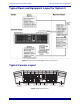
System Control Connections
Ethernet
Several intelligent system components are connected via RJ45 Ethernet through a EuCon
Ethernet hub. These devices include:
• SC262 System Computer
• PC254d Digital Pilot Computers
• PC254i Interface Computer
• CM408 Eight-channel Modules
• CM401 Master Fader Module (console center section)
• CM402 Expanded Channel Module (console center section)
• CM403 Film and Joystick Panels
KVM Extender
The KVM Extender cable is a Category 5 UTP cable, however it does not carry Ethernet
data like the system components. The KVM Extender requires its own dedicated cable. Its
maximum length is 400 ft (120 m).
Monitor, Trackball, and Keyboard
The SC262 System Computer provides master control for the entire system. A monitor,
trackball, and keyboard located in the control room connect to this computer and control
mixing, routing, and file management. A KVM Extender is typically used which routes
these signals from the machine room to the control room through a single multipair cable
built into the console ethernet harness.