Heating A Division of A.F. Gason Pty Ltd Jindara Derwent High Efficiency Gas Log Fire Operation & Installation Instructions REV. B SERIAL NO.
Derwent High Efficiency Gas Log Fire 2 Contents Warnings and name plate details ...............................................................................................................................................3 Product features and safety features ..........................................................................................................................................4 Installation................................................................................................
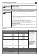
Derwent High Efficiency Gas Log Fire ! WARNING ! WARNING Safety Warnings 3 Read and follow these instructions carefully before installing and using this appliance. SAVE THESE INSTRUCTIONS • DO NOT – operate this appliance before reading this instruction manual. • DO NOT – place articles on or against this appliance. • DO NOT – store chemicals, flammable materials or spray aerosols near this appliance • DO NOT – operate with panels, covers or guards removed from this appliance.
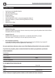
Derwent High Efficiency Gas Log Fire 4 Product Features • • • • • • • • • Zero Clearance to Combustible Materials 5.05 Star Energy Rating Manual or thermostat controls Electronic ignition Variable heat settings External combustion air intake - prevents de-oxygenation of room air. Delayed start room fan - prevents cold air being circulated at start-up. Power flue.
Derwent High Efficiency Gas Log Fire 5 Installation ! WARNING Installation THE INSTALLATION OF THIS APPLIANCE MUST BE CARRIED OUT AS PER THIS MANUAL. WE RECOMMEND THAT YOU USE A QUALIFIED INSTALLER TO CARRY OUT THE INSTALLATION IN ACCORDANCE WITH AS 5601/AG 601 (GAS INSTALLATION CODE), MANUFACTURER’S INSTALLATION INSTRUCTIONS, LOCAL GAS FITTING REGULATIONS AND MUNICIPAL BUILDING CODES. If you have any other enquiries, please contact the dealer from whom you purchased your heater.
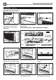
Derwent High Efficiency Gas Log Fire 6 Installation (Continued) REMOVING THE DOOR ASSEMBLY Figure (1). Remove screws from lower fascia panel at either end. Place panel carefully aside so as not to scratch or damage panel. Figure (2). Remove screws from bottom of door assembly... Figure (3). ...and top of door assembly. INSTALLING THE LOGSET - TAKE EXTREME CARE - FRAGILE! Logset components 2 pins Front Log Cross Ignitor Tube (Fixed to front log) Back Log Cross Log Figure (4).
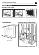
Derwent High Efficiency Gas Log Fire Installation 7 (Continued) INSTALLING THE LOGSET (continued) Figure (7). Place right twig in position. CLEARANCE DIMENSIONS Figure (9). Replace the door assembly and secure the four screws. Ensure arrows point downwards, that are on the mounting point of the door frame. Figure (8). Place left twig in position.
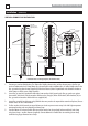
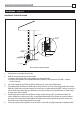
Derwent High Efficiency Gas Log Fire 8 Installation (Continued) VERTICAL CHIMNEY FLUE INSTALLATION Jindara AGA Approved gas cowl (Supplied by Jindara) Gas Cowl Hose clamps (Supplied) Flue Brackets (Supplied) Flashing (Not supplied) Flue weather shield (Supplied) 4.6 metres max. 50mm exhaust flexi tube (Supplied) 60mm air intake flexi tube (Supplied) 1/2˝ copper pipe Installation into an existing fireplace (Vertical Flue Unit) 1. Connect gas cowl to flexible tubes. The 50mm dia.
Derwent High Efficiency Gas Log Fire Installation 9 (Continued) HORIZONTAL FLUE INSTALLATION False fireplace Hose clamps (Supplied) Flexi tubes (Supplied by Jindara) Jindara AGA Approved gas cowl (Supplied by Jindara) 1/2˝ copper pipe Rear vent balanced flue installation 1. Determine the exact location for the heater 2. Mark the exact location for the wall penetration a. Determine that you will not be cutting through any vertical wall studs. b.
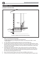
Derwent High Efficiency Gas Log Fire 10 Installation (Continued) HORIZONTAL FLUE INSTALLATION Flexi tubes (Supplied by Jindara) Eureka AGA Approved gas cowl (Supplied by Jindara) MAX OVERALL FLUE PIPE LENGTH 4.6M Min. flue slope 25mm per metre. Use hangers every 500mm to avoid water trap. 1/2˝ copper pipe Installation on stump floor and internal wall. (Flue kit under floor.) 1. Mark the exact location for the wall penetration a.
Derwent High Efficiency Gas Log Fire Installation 11 (Continued) INSTALLATION INTO A FALSE FIREPLACE Jindara AGA Approved gas cowl (Supplied by Jindara) See detail B Weather seal flashing (Not supplied) Flue Pipe (Supplied) See detail A 1/8˝ pop rivet (x4) Flue pipe Flue pipe support brackets Flexi tubes (Supplied by Jindara) Suitable nail or screw (x4) False fireplace Bottom of roof truss Detail A Flue gas cowl 1/8˝ pop rivet (x6) Flue cowl bracket (x3) Flue pipe 1/2˝ copper pipe Detail B
Derwent High Efficiency Gas Log Fire 12 Operating your Jindara Derwent ! WARNING Read these instructions DO NOT ATTEMPT TO OPERATE THIS APPLIANCE WITHOUT READING AND UNDERSTANDING THESE OPERATING INSTRUCTIONS THOROUGHLY. FAILURE TO OPERATE THIS APPLIANCE PROPERLY MAY CAUSE UNDUE DAMAGE TO THE APPLIANCE. The Jindara Derwent Gas log space Heater has been designed for simple operation to provide you with the highest heat output.
Derwent High Efficiency Gas Log Fire 13 RF Thermostat FEATURES • • • • Backlit Liquid Crystal Display Seven Function Keyboard Four Individual Programs per Day UHF Radio Frequency LCD DISPLAY FEATURES • • • • • • • Battery type: 2 x AA batteries • • Battery Life: approximately 12 months Transmission frequency: 433.
Derwent High Efficiency Gas Log Fire 14 RF Thermostat (Continued) LCD DISPLAY INDICATIONS Feature Symbol Description Time of the day Displays time of the day in hours and minutes, AM or PM. The time is displayed when the thermostat is on or off. Day of week Displays the current day of the week. The day is displayed when the thermostat is on or off. Temperature display Displays the current temperature. C° is the default but F° is available.
Derwent High Efficiency Gas Log Fire RF Thermostat 15 (Continued) BUTTON FUNCTIONS Button Function Description PWR ON/OFF Switches the thermostat on and off. If the thermostat is off, pressing and releasing the PWR button will turn the thermostat on to the most recently selected working mode. Toggles between automatic and manual mode. A/M Automatic / Manual OK Enter Accepts the current function and advances to the next function. UP Increment hours, minutes, day or temperature.
Derwent High Efficiency Gas Log Fire 16 RF Thermostat (Continued) INITIAL SETUP On/Off Press and release the button. If the thermostat is off, pressing and releasing will turn the thermostat on to the most recently selected working mode. Setting the day of the week and time With the thermostat off, press and hold the button for 2 seconds or longer to initiate programming the time. ‘Time‘, the ‘hour setting‘ and ‘AM/PM’ will flash. • Setting the hour function 1.
Derwent High Efficiency Gas Log Fire RF Thermostat 17 (Continued) MANUAL MODE - THERMOSTAT (Continued) The Room Fan speed settings are as follows: - Speed 1 – difference between room temp. and set temp. is 0-1°C e.g. room 20.5°C – set 21°C - Speed 2 – difference between room temp. and set temp. is 1-2°C e.g. room 21°C – set 22°C - Speed 3 – difference between room temp. and set temp. is 2-3°C e.g.
Derwent High Efficiency Gas Log Fire 18 RF Thermostat (Continued) PROGRAMMING Each day of the week can be programmed individually for 4 periods P1, P2, P3 and P4, making a total of 28 programmed periods. Alternatively, a weekday program can be set, so the same program is used for Monday-Friday. Similarly, a weekend program can be set for Saturday-Sunday. The entire week can also have the same program. Alternatively, a weekday or weekend program can be set with individual programs for the remaining days.
Derwent High Efficiency Gas Log Fire RF Thermostat 19 (Continued) PROGRAMMING SCREEN DISPLAYS Set period day - Days of the week flash Set hours - Time & hours flash Set minutes - Time & minutes flash Period 2 - For periods 2,3 &4, repeat steps as for Period 1 Period 3 Period 4 PROGRAM MODE - FACTORY DEFAULT SETTINGS Time Period Start Time Heat Temperature (°C) Period 1 6.00 am 20 °C Period 2 8.30 am 15 °C Period 3 5.00 pm 21 °C Period 4 10.
Derwent High Efficiency Gas Log Fire 20 RF Thermostat (Continued) PROGRAM MODE - YOUR SETTINGS Weekdays Time Period Start Time Heat Temperature (°C) Period 1 am °C Period 2 am °C Period 3 pm °C Period 4 pm °C Start Time Heat Temperature (°C) Period 1 am °C Period 2 am °C Period 3 pm °C Period 4 pm °C Weekend Time Period SETTINGS Change between °C and °F The thermostat temperature display can be set to °C or °F. The default is °C.
Derwent High Efficiency Gas Log Fire RF Thermostat 21 (Continued) Teaching RF thermostat ID code to control unit (continued) 4. The 3 LEDs on the front panel will flash once to indicate that the Thermostat ID has been learnt successfully. If the LEDs do not flash, repeat steps 1 to 3. 5. After the Thermostat ID is successfully learnt by the Receiver/Controller, pressing the button on the Thermostat will switch the Thermostat ON.
Derwent High Efficiency Gas Log Fire 22 RF Thermostat (Continued) RECEIVER/CONTROLLER (Continued) Button or LED Function Fan Increase Button • The Fan speed is linked to the Flame setting. • At Flame setting 1 & 2, the Fan can only operate at Low speed. • At Flame setting 3 & 4, the Fan can be selected to operate between Low, Medium and High. • Pressing and releasing this button once will increase the Fan speed to the next available setting.
Derwent High Efficiency Gas Log Fire RF Thermostat 23 (Continued) QUICK REFERENCE TABLE Function Action Switch on / off Press and release the button Change between manual and automatic mode Press and release button Increase / decrease temperature Press and release or button Set the clock and the day of the week • With the thermostat off, press and hold the T button until the time, hour and AM/PM flash.
Derwent High Efficiency Gas Log Fire 24 RF Thermostat (Continued) TROUBLESHOOTING Problem Corrective Actions Fireplace comes on at the wrong time • Check the programmed period start and finish times are correct • Check that AM or PM is correctly set Fireplace comes on at the wrong temperature • Check the programmed period temperature setting is correct • Check that °C or °F is correctly specified The time or day of the week is incorrect • Reset the time and day of the week as was required
Derwent High Efficiency Gas Log Fire 25 Operating your Jindara Derwent (Continued) SAFETY PRECAUTIONS IMPORTANT POINTS: • DO NOT place articles or clothing on or against this appliance • DO NOT use or store flammable materials near this heater • DO NOT place any item containing liquid on the heater • DO NOT spray aerosol in the vicinity of this appliance when it is in operation • ALWAYS supervise young children near the appliance It is recommended that a secondary guard be used to prevent access
Derwent High Efficiency Gas Log Fire 26 Maintenance ! WARNING Read these instructions MAINTENANCE SHOULD BE CARRIED OUT BY AUTHORISED PERSONS ONLY. ENSURE POWER IS DISCONNECTED BEFORE ANY MAINTENANCE TAKES PLACE. REMOVING THE FASCIA PANELS Figure (1). Remove screws from lower fascia panel at either end. Figure (2). Disconnect connector from rear of controls, and remove lower fascia. Figure (3). Remove two screws from the top part of the outer fascia panel... Figure (4). ...
Derwent High Efficiency Gas Log Fire Maintenance 27 (Continued) CHANGING THE INJECTORS Figure (1). Remove front burner wire from socket on Brahma Control Module. Figure (2). Lift out front burner assembly, Figure (3). Unbolt the rear injector. Note: front and rear injectors are now accessible. Rear injector can be unbolted with rear burner still in place. Figure (4). Replace the rear injector with an appropriate size. (Refer to name plate on page 3.) Figure (5).
Derwent High Efficiency Gas Log Fire 28 Maintenance (Continued) TO REMOVE COMPONENT TRAY FOR SERVICE Figure (1). Disconnect power connector shown. Figure (2). Disconnect earth terminal of power lead from earth terminal bolt. Figure (3). Place power lead to side. Figure (4). Disconnect connectors shown x 2. Figure (5). Remove the fan screws as shown previously. Figure (6). Disconnect ignitor leads x 3. Figure (7). Remove gas flexitube from gas control valve right hand side. Figure (8).
Derwent High Efficiency Gas Log Fire 29 Troubleshooting Appliance fails to ignite Unit will not operate on Low. Room fan not operating. Unit cuts out after a period of time then cycles on and off. Excessive carbon (soot) deposits on inside of firebox, logs, and/or glass. No gas or supply pressure insufficient Ensure gas supply connected, purged, and pressure appropriate No electrical supply. Ensure unit plugged in and switch is on, check supply fuse. Incorrectly wired power point. Check supply.
Derwent High Efficiency Gas Log Fire 30 Troubleshooting (Continued) Excessive flame height. Excessive flame “lift off”. Unit fails to heat. Unit goes out after period of time and will not relight. Excessive heat above unit after shut down. Incorrect gas type or pressure setting. Ensure correct gas type, injector size, and pressure setting. Loose Door Ensure door is properly sealed and arrows on door tabs point down. Flue or inlet blockage. Clear blockage. Recirculation of flue gases.
Derwent High Efficiency Gas Log Fire Wiring Diagram 31
Derwent High Efficiency Gas Log Fire 32 Dimensions 799 TOP VIEW 375 894 753 300 Inlet Air (60mm dia.) 668 236 Flue Exhaust (50mm dia.
Derwent High Efficiency Gas Log Fire 33 Parts List Fan Assembly - GPN221272 Switch Air Pressure GPN221275 Exhaust fan complete - GPN221292 Brahma Controller CE31V - GPN221256 Controller Sigma 845 - GPN221273 Valve Modulating - GPN221288 Injector Resistor - GPN221281 Spark Electrode GPN221330 LPG Front O 1.25 - GPN221695 LPG Rear O 1.5 - GPN221706 NAT Front O 2.15 - GPN221270 NAT Rear O 2.
Derwent High Efficiency Gas Log Fire 34 Complete Log Set - GPN221327 2 pins - GPN 223398 Front Log - GPN222750 Cross Ignitor Tube (Fixed to front log) GPN221802 Back Log - GPN222749 Left twig - GPN222751 Cross Log - GPN222753 Right twig - GPN222752
Derwent High Efficiency Gas Log Fire 35 WARRANTY 1. Subject to Clauses 2 & 3 of this warranty, Jindara Heating (‘Jindara’) warrants the following components of its heaters against defects in workmanship and/or materials for the following periods from the date of purchase.
SERIAL NO : 221300 - PLEASE LEAVE THIS DOCUMENT WITH CUSTOMER AFTER COMPLETION 1. Ensure power point for heater is accessible or has an isolation switch near heater. NOTE: keep power OFF at this Stage (NO EXTENSION LEADS). Remove facia and door from heater then reconnect lower false panel to RJ45 lead (white control box) so switch decal is visible. Check supply gas pressure going into gas valve using a manometer (refer manual pg 27 Fig 3. for purge port location)- LPG should be 2.
SERIAL NO : 224924 COMMISSIONING CHECKLIST 221300 - INSTALLER PLEASE TICK PLEASE LEAVE THIS DOCUMENT WITH CUSTOMER AFTER COMPLETION 8. Once heater has reached the high setting, check the pressure (referring to page 3 of the manual for pressure settings) and adjust if necessary. NOTE: the acceptable range for high on LPG is between 1.35 – 1.55kPa and the acceptable range for high on Natural Gas is between 0.55 – 0.65kPa 9. 10.