EUREKA MICROPHONE PREAMPLIFIER COMPRESSOR PARAMETRIC EQUALIZER USER’S MANUAL version 3.0 © 2003-2007, Pr e S o n u s A u d i o E l e c t r o n i c s , I n c o r p o r a t e d . A l l r i g h t s r e s e r ve d .
W A R R A N T Y PreSonus Limited Warranty PreSonus Audio Electronics Inc. warrants this product to be free of defects in material and workmanship for a period of one year from the date of original retail purchase. This warranty is enforceable only by the original retail purchaser. To be protected by this warranty, the purchaser must complete and return the enclosed warranty card within 14 days of purchase.
TABLE OF CONTENTS 1 Overview 1.1 Introduction 4 1.2 Features 4 2 Controls & Connections 2.1 Front Panel Basic Layout 7 2.2 Preamplifier 9 2.3 Compressor 10 2.4 Equalizer 12 2.5 Master 13 2.6 Back Panel 13 2.7 Power Supply 14 3 Operation 3.1 Microphones 15 3.2 Send and Return 15 3.3 192k/24-Bit Digital Output Card 16 3.4 Application Settings 17 4 Technical 3.
1 OVERVIEW 1.1 INTRODUCTION Thank you for purchasing the PreSonus EUREKA. PreSonus Audio Electronics has designed the EUREKA utilizing high-grade components to insure optimum performance for an infinite period of time. We believe the EUREKA to be an exceptional sounding unit and an exceptional value. We encourage you to contact us at 1-800-750-0323 with any questions or comments you may have regarding your PreSonus equipment.
OVERVIEW chance of over-driving the input and avoiding distortion. • +22dBu Headroom. The EUREKA mic-pre has +22 dBu of headroom. This feature gives you wide dynamic range and excellent transient response characteristics. • Saturation Control. The EUREKA offers a very high quality transformer and features an SATURATION control (this control adjusts the drain current on the input FET amplifier altering the even harmonic levels of the signal being passed) with an adjustment range of 0% to 100%.
OVERVIEW 3-Band Parametric Equalizer. Total tonal control is what the Equalizer section provides. The EQ will let you fine tune the sound to suit your taste with exacting precision. • Bypass Switch. A bypass switch is provided to audition the signal in an equalized version as compared to a direct unaffected signal. • Variable Q. Adjusts the width of the frequency band between wide and narrow during equalization. • EQ►COMP. Switches the order of the signal chain putting EQ before the Compressor.
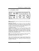
2 CONTROLS & CONNECTIONS 2.1 FRONT PANEL BASIC LAYOUT The front panel of the EUREKA is divided into four sections – Preamplifier, Compressor, Equalizer and Master.
CONTROLS & CONNECTIONS Compressor Section: • Level Control (Attack, Release, Ratio, Threshold, Gain) • Soft Knee Switch • Bypass Switch • Hi-pass Sidechain Filter Equalizer Section: • 3 Band Parametric • 80 Hz Filter Switch • Bypass Switch Master Section: • Level Control • Gain Reduction to Meter Button 8
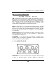
CONTROLS & CONNECTIONS 2.2 PREAMPLIFIER GAIN: Provides +52dB of gain for the microphone input and +44dB of gain for the instrument input. IMPEDANCE SELECTOR: Selects the amount of resistance that is applied to the microphone input. This selector allows you to match (or intentionally mismatch) the input impedance of the Eureka with the impedance of your microphone. As the Eureka’s impedance is lowered, different filtering effects can result delivering a tailored sound for a particular application.
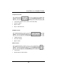
CONTROLS & CONNECTIONS XLR connector wiring for Phantom Power Pin 1= GND Pin 2= +48V Pin3= +48V PAD: Engaging the Pad switch provides -20dB of attenuation with the push of a button. This is a very useful feature for rapidly reducing the level coming into the EUREKA and thus preventing the input signal from over-driving (distorting) the input. This may occur due to high output level from a microphone or other device.
CONTROLS & CONNECTIONS Basically, as you turn the Threshold knob counter-clockwise, the input signal is compressed. (If you have a ratio setting of greater than 1:1.) RATIO: Sets the compression slope. This is defined as the output level versus the input level. For example, if you have the Ratio set to 2:1, any signal level above the Threshold setting will be compressed at a compression ratio of 2:1.
CONTROLS & CONNECTIONS 2.4 EQUALIZER The EQ is divided into three sections or bands (Low, Mid and High) Each band has the following controls: GAIN: Controls the amount of cut or boost of the corresponding frequency. Each gain control offers +/-10dB of attenuation. FREQUENCY: Selects the center frequency of equalization. If the gain is set to 0, this control will have no effect. Q (Bandwidth): Controls the width of the frequency being adjusted.
CONTROLS & CONNECTIONS 2.5 MASTER MASTER (LEVEL): This control adjusts the output level of the EUREKA. It functions as a master fader for the entire processing strip. It is useful for adjusting the overall output level up or down to match the optimum input level of a recorder, mixer, etc. GR TO METER: When pushed the VU meter reads Gain Reduction of the Compressor. When not pushed, the VU meter reads output level. 2.
CONTROLS & CONNECTIONS All Input and Output connectors are servo balanced. XLR or ¼” TRS with the following wiring standard: XLR/TRS PIN 1 / Sleeve GND PIN 2/ Tip High (+) PIN 3/ Ring Low (-) INSERT: Return and Send connectors are provided for use in conjunction with audio process devices such as reverbs, delays, de-essers, etc. NOTE: The LINE IN jack does not work unless the LINE button on the front of the unit is pushed in. 2.
3 OPERATION 3.1 MICROPHONES The Eureka works great with all types of microphones including dynamic, ribbon and condenser microphones. Dynamic microphones and ribbon microphones are generally lower output devices and require no external power source. Condenser microphones are generally more sensitive than dynamic and ribbon microphones and typically require external 48V phantom power.
OPERATION into the external processor, then back into the EUREKA. The final, processed signal will be available at the EUREKA output connector. The Send and Return signal will be inserted after the microphone preamplifier, before the compressor. 3.3 192K/24-BIT DIGITAL OUTPUT CARD (OPTIONAL) A 192K/24-BIT Digital Output Card is available as an option for the PreSonus EUREKA. It has AES/EBU and SPDIF output connectors, as well as, an auxiliary ¼” TRS analog Line input connector.
OPERATION 3.4 APPLICATION SETTINGS The following are application settings to get you started in using your Eureka. Feel free to experiment by pushing any and all buttons and turning knobs to their extreme values - remember there are no rules when creating music. Let your imagination and ear guide and direct the way you set your Eureka. Note that the application settings do not include the main preamplifier controls: GAIN, IMPEDANCE and SATURATE.
OPERATION 2. Acoustic Guitar Compressor settings Thresh Ratio Gain Soft Bypass Attack Release SC-HP -20 3 +2 In Out Mid Fast 10 Equalizer settings LOW MID HIGH EQ>Comp Q Gain Freq Q Gain Freq Q Gain Freq Out n/a 0 n/a Nar -2 3k Wide +3 18.5k Nar = Narrow Q 3.
OPERATION 4. Bass Guitar Compressor settings Thresh Ratio Gain Soft Bypass Attack Release SC-HP -15 7 +4 In Out MF MS 10 Equalizer settings LOW MID HIGH EQ>Comp Q Gain Freq Q Gain Freq Q Gain Freq Out Wide +6 85 MN -3 2.2k n/a 0 n/a MN – Medium Narrow, MW – Medium Wide 5.
OPERATION 6. Kick Drum Compressor settings Thresh Ratio Gain Soft Bypass Attack Release SC-HP -18 5 +2 Out Out MF MF 80 Equalizer settings LOW MID HIGH EQ>Comp Q Gain Freq Q Gain Freq Q Gain Freq In Wide +8 60 Nar -8 400 Wide +6 2.5k 7.
OPERATION 8.
4 TECHNICAL EUREKA SPECIFICATIONS Channels ....................................................................................................ONE Dynamic Range.....................................................................................>115dB Headroom .............................................................................................+22dBu Frequency Response .................................................................10Hz to 50kHz Internal Operating Level.............................
TECHNICAL Equalizer Low Band (+/-10dB) ................................................................... 20Hz – 300Hz Mid Band (+/-10dB) ....................................................................200Hz to 3kHz High Band )+/- 10dB) ..................................................................2kHz – 20kHz Q (variable all bands) .................................Q=0.4 to 2 (3 octave to 2/3 octave) Master Output Fader ...........................................................................