---cooking USE AND CARE GUIDE MODELNO. EGZ70CTFGSXS EMBRACE EUROPEAN QUALITY+PASSION www. eu roappli a nces.com .
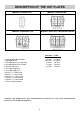
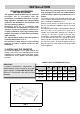
DESCRIPTION OF THE HOT PLATES MODEL: EPZ2GFFDS MODEL: EGZ600FDS MODEL: EGZ70CTFGSX-EGZ700FGS MODEL: EGZ60WCTSX NATURAL U-LPG 1 Ultra rapid gas burner/WOK 2 Rapid gas burner 3 Semirapid gas burner right front 4 Semirapid gas burner left back 5 Auxiliary gas burner 6 Trivet pan support 2F 7 Trivet pan support 1F 8 Burner n° 1 control knob 9 Burner n° 2 control knob 10 Burner n° 3 control knob 11 Burner n° 4 control knob 12 Burner n° 5 control knob 13 Electric ignition button 14.5 MJ/h 12.0 MJ/h 7.
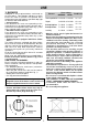
USE 1) BURNERS A diagram is screen-printed above each knob on the front panel. This diagram indicates to which burner the knob in question corresponds. After having opened the gas mains or gas bottle tap, light the burners as described below: - manual ignition Push and turn the knob corresponding to the required burner in an anticlockwise direction until it reaches the full on position (large flame fig. 1), then place a lighted match near the burner.
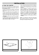
USE Notes: use of a gas cooking appliance produces heat and moisture in the room in which it is installed. The room must therefore be well ventilated by keeping the natural air vents clear (fig. 3) and by activating the mechanical aeration device (suction hood or electric fan fig. 4 and fig. 5). Intensive and lengthy use of the appliance may require additional ventilation. This can be achieved by opening a window or by increasing the power of the mechanical exhausting system if installed.
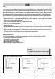
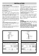
In the event where persistent marks appear: immediately clean affected areas with stainless steel cleaner, using a clean damp soft cloth. Ensure surface is rinsed and thoroughly clean of all marks and stainless steel cleaner. IMPORTANT: always disconnect the appliance from the gas and electricity mains before carrying out any cleaning operation. 2) HOT PLATE Periodically wash the hot plate, the enamelled steel pan support, the enamelled burner caps “C” and the burner heads “T” (see fig.
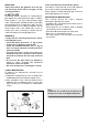
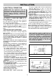
INSTALLATION TECHNICAL INFORMATION FOR THE INSTALLER Never leave the packacing materials (cardboard, bags, polystyrene foam, nails, etc.) within children’s reach since they could become potential sources of danger. The measurements of the opening made in the top of the modular cabinet and into which the hot plate will be installed are indicated in fig. 7. Always comply with the measurements given for the hole into which the appliance will be recessed (see fig. 7).
4) FIXING THE COOKTOP INSTALLATION - Fix the hob with the proper brackets “S” and fit the prominent part into the porthole “H” on the bottom; turn the screw “F” until the bracket “S” stick on the top (fig. 9). - When the appliance is installed so that the base can be touched, we recommend fitting a protecting shield. This shield must be at least 60 mm below the base of the bench top (fig. 7). Timber or other suitable material may be used provided it is capable of withstanding the appliance temperatures.
5) GAS CONNECTION INSTALLATION Natural Gas Natural Gas installations require the connection of a gas regulator at the appliance. This regulator is supplied with the appliance on purchase. Assemble the regulator (noting the gas flow direction) and transition pieces (supplied with the appliance), in accordance with figure 10. The transition piece on the supply side of the regulator must be provided by the installer.
INSTALLATION 6) ELECTRICAL CONNECTION - The power supply cable must be positioned so that no part of it is able to reach an overtemperature of 75 K. - Never use reductions, adapters of shunts for connection since these could create false contacts and lead to dangerous overheating. When the appliance is connected straight to the electricity main: - Install an omnipolar circuit-breaker between the appliance and the electricity main.
ADJUSTMENTS 7) TAPS Always disconnect the appliance from the electricity main before making any adjustments. All seals must be replaced by the technician at the end of any adjustments or regulations. Our burners do not require primary air adjustment. a) Data Label The Data Label is located on the underside of the hotplate. A duplicate Data Label is supplied to adhere in an accessible area next to the hotplate.
CONVERSIONS 8) U-LPG TO NATURAL GAS CONVERSION PROCEDURE 9) NATURAL GAS TO U-LPG CONVERSION PROCEDURE 1. Remove each burner cap and burner skirt. 2. Remove the U-LPG main injector with a 7 mm/VF tube spanner and replace with the appropriate size Natural Gas main injector for each burner. The following injector sizes are required for Natural Gas: Burner Main injector 1. Remove each burner cap and burner skirt. 2.
CONVERSIONS 10) REPLACING THE INJECTORS burners must be regulated as explained in paragraphs 7. The technician must reset any seals on the regulating or pre-regulating devices. The envelope with the injectors and the labels can be included in the kit, or at disposal to the authorized customer Service Centre. For the sake of convenience, the nominal rate table also lists the heat inputs of the burners, the diameter of the injectors and the working pressures of the various types of gas.
SERVICING WARNING: servicing should be carried out only by authorised personnel. Greasing the taps (see fig. 20 - 21) If a tap becomes stiff to operate, it must be immediately greased in compliance with the following instructions: - remove the tap. - Clean the cone and its housing using a cloth soaked in diluent. - Lightly spread the cone with the relative grease. - Fit the cone back in place, operate it several times and then remove it again.
SERVICING CABLE TYPES AND SECTIONS TYPE OF HOT PLATE Gas hot plate TYPE OF CABLE H05 RR - F SINGLE - PHASE POWER SUPPLY Section 3 X 0.75 mm2 ATTENTION!!! If the power supply cable is replaced, the installer should leave the ground wire longer than the phase conductors (fig. 22) and comply with the recommendations given in paragraph 6. FIG.
TECHNICAL ASSISTANCE AND SPARE PARTS Before leaving the factory, this appliance will have been tested and regulated by expert and specialized personnel in order to guarantee the best performances. Any repairs or adjustments which may be subsequently required may only be carried out by qualified personnel with the utmost care and attention.