
Product Manual - NEW cover


ADJUSTMENTS
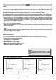
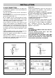
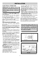
FIG. 14/A
10
Always disconnect the appliance from the
electricity main before making any adjustments.
All seals must be replaced by the technician at
the end of any adjustments or regulations.
Our burners do not require primary air
adjustment.
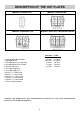
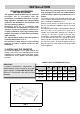
a) Data Label
The Data Label is located on the underside of the
hotplate. A duplicate Data Label is supplied to
adhere in an accessible area next to the hotplate.
This hotplate is suitable for Natural Gas and U-LPG ;
ensure that the available gas supply matches the
Data Label.
b) Before Leaving
Check that there are no gas leaks, but do not use a
naked flame to detect gas leaks. Ignite all burners
to ensure correct operation of gas valves, burners,
ignition and if fitted, flame failure valves. Turn gas
taps to low flame position and observe stability of
the flame. When satisfied with the hotplate, please
instruct the user on the correct method of operation.
In case the appliance falls to operate correctly after
all checks have been carried out, refer to the
authorised service provider in your area.
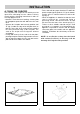
7) TAPS
Our taps are suitable for all the gas, they are male
conical type at one way.
“Reduced rate” adjustment
- Switch on the burner and turn the relative knob to
the “Reduced rate” position (small flame fig. 1).
- Remove knob “M” (fig. 14 and 14/A) of the tap,
which is simply pressed on to its rod. The by-pass
for minimal rate regulation can be: beside the tap
(fig. 14) or inside the shaft. In any case, to access
to regulation, it can be done trought the insertion
of a small screwdriver ‘’D’’ beside the tap (fig. 14)
or in the hole ‘’C’’ inside the shaft of the tap
(fig 14/A). Turn the throttle screw to the right or left
until the burner flame has been adequately
regulated to the “Reduced rate” position.
The flame should not be too low: the lowest small
flame should be continuous and steady. Re-
assemble the several components.
It is understood that only burners operating
with Natural gas should be subjected to the
above mentioned adjustments. The screw must
be fully locked when the burners operate with
Liquid gas.
FIG. 14