
Product Manual - NEW cover


CONVERSIONS
FIG. 15
BURNER ARRANGEMENT ON THE HOT PLATE
BURNERS
GAS
NORMAL
PRESSURE
(kPa)
INJECTOR
DIAMETER
(1/100 mm)
N O M I N A L
HEAT
INPUT (MJ/h)
MAX.
BY PASS
N°
DESCRIPTION
1/100 mm
1
ULTRA RAPID/WOK
U-LPG
NATURAL
2.75
1.00
94
176
11.4
14.5
85
1/2
2
RAPID
U-LPG
NATURAL
2.75
1.00
91
155
10.4
12.0
45
1/4
3
SEMIRAPID
RIGHT FRONT
U-LPG
NATURAL
2.75
1.00
70
120
6.2
7.1
35
1/4
4
SEMIRAPID
LEFT BACK
U-LPG
NATURAL
2.75
1.00
70
120
6.2
7.1
35
1/4
5
AUXILIARY
U-LPG
NATURAL
2.75
1.00
53
90
3.5
4.1
32
1/4
TABLE
12
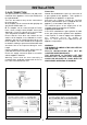
10) REPLACING THE INJECTORS
The burners can be adapted to different types of
gas by mounting injectors suited to the type of gas
in question. To do this, first remove the burner tops
using a wrench “B”. Now unscrew injector “A” (see
fig. 15) and fit a injector corresponding to the
utilized type of gas in its place.
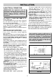
It is advisable to strongly tighten the injector in
place.
After the injectors have been replaced, the
burners must be regulated as explained in
paragraphs 7. The technician must reset any
seals on the regulating or pre-regulating devices.
The envelope with the injectors and the labels can
be included in the kit, or at disposal to the
authorized customer Service Centre.
For the sake of convenience, the nominal rate table
also lists the heat inputs of the burners, the
diameter of the injectors and the working pressures
of the various types of gas.