cooking USAGE AND CARE GUIDE PRODUCT CODE: EM6 0 CSX/ EM9 0 CSX
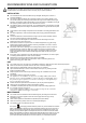
RECOMMENDATIONS AND SUGGESTIONS The instructions for use apply to several versions of this appliance. Accordingly, you may find descriptions of individual features that do not apply to your specific appliance. INSTALLATION The manufacturer will not be held liable for any damages resulting from incorrect or improper installation. The minimum distance between the supporting surface for the cooking vessels on the hob and the lowest part of the range hood.
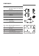
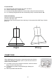
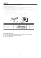
COMPONENTS Ref. Qty. 1 1 Hood Body, complete with: Controls, Light, Blower, Filter. 2.1 1 Lower Decorative Chimney 2.2 1 Upper Decorative Chimney ( optional ) 3 1 Flange ( optional ) 4 1 Exhaust Pipe 5 2 The Activated Charcoal filter ( optional ) Qty. 1 Product Components 4 2.2 3 5 2.1 Documentation 1 Instruction Manual Ref. Qty.
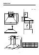
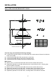
DIMENSIONS unit:mm 225 258 472 171 171 472 600/900 Min. 650mm Min.
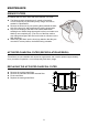
INSTALLATION WALL DRILLING AND BRACKET FIXING 40 (2) B X 40 80 80 (1) 920-1020 190 A C 170 170 (3) Option 1 2 3 4 Chimney 400+0 400+300 400+390 500+490 X / 390-620 390-710 490-910 Vertical reference line As a first step, proceed with the following drawings: A vertical line up to the ceiling or up to the upper limit, at the center of the area in which the hood is to be fitted. A horizontal line A at 920-1020 mm above the cooker top.
Fix the brackets : Drill holes at the marked points with a ɸ10 mm drill bit. Insert the Wall Plugs 11 into the holes. Fix the hood fixing bracket 20 with 3 screws 10 (5 x 50) at the horizontal line A. Fix a Chimney fixing bracket 21 with 2 screws 10 (5 x 50) at the horizontal line B. Hook the hood body Hook the hood body to the bracket 20. Level the hood body itself. Remove the filter from the inside of the hood body, fix the screws 10 to Wall Plugs 11 at the points (3).
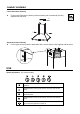
CHIMNEY ASSEMBLY Lower Decorative Chimney Fix the Lower Decorative Chimney to the hood body with 2 screws 12 (4.2 x 9.5) supplied with the hood. B Upper Decorative Chimney Fix the upper chimney onto the bracket 21 with 2 screws 12 (4.2 x 9.5) supplied with the hood. USE Speed adjustment. (For some models) OFF MOTOR SWITCH: Press on this switch to stop the motor operation. SPEED SWITCH: Press on this switch, the motor runs at LOW speed.
MAINTENANCE GREASE FILTERS CLEANING METAL SELF-SUPPORTING GREASE FILTERS The filters must be cleaned every 2 months of operation, or more frequently for particularly heavy usage, and can be washed in a dishwasher. Remove the filters one by one pushing them towards the back side of the hood unit and simultaneously pulling downwards. Any kind of bending of the filters has to be avoided when washing them. Before fitting them again into the hood make sure that they are completely dry.
LIGHTING LIGHT REPLACEMENT (Completed by professionals) Replacing the light modules You cannot replaced the light bulbs, the entire light module has to be replaced. When changing the light modules, the contacts are live. Before changing the light module(s), unplug the appliance from the mains or switch off the circuit breaker in the fuse box. Remove the grease filter . Disconnect the terminal of LED light. Press LED light on the back of the front plate, take the LED light out.
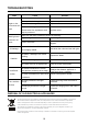
TROUBLESHOOTING Fault Cause Light on, but motor does not work Solution The blades are blocked. Check the blades. The capacitor is damaged. Replace capacitor. The motor is damaged. Replace motor. The internal wiring of motor is cut off/ disconnected. An unpleasant smell Replace motor. may be produced. Both light and motor do not work Oil leakage Apart from the above mentioned, check the following: Light damaged. Replace lights. Power cord loose. Connect the wires as the electric diagram.
Pronto Service + Support: 1800 440 335 Email: service@eurostylegroup.com.au HEAD OFFICE 65 Glynburn Road, Glynde SA 5070 Ph: 08 8165 1012 www.euroappliances.com.