Installation Guide and Users Manual SPAGNA VETRO 218 Series IMPORTANT: Read and save these instructions.
Important Safety Notice Read all Instructions before Installing and operating this appliance • • • • • The installation in this manual is intended for qualified installers, service technicians or persons with similar qualified background. Installation and electrical wiring must be done by qualified professionals and in accordance with all applicable codes and standards, including fire-rated construction. DO NOT attempt to install this appliance yourself.
Important Safety Notice Read all Instructions before Installing and operating this appliance • • • Clean ventilating fan frequently. Always use appropriate cookware and utensils size. Always use cookware appropriate for the size of the surface element. To reduce the risk of injury to persons in the event of a stove top grease fire: • • • SMOTHER FLAMES with a close-fitting lid, cookie sheet, or metal tray, then turn OFF the burner. BECAREFUL TO PREVENT BURNS. NEVER PICK UP A FLAMING PAN—you may be burned.
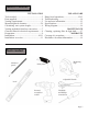
Table of Contents INSTALLATION Tools needed....................................................3 Parts supplied...................................................4 Venting requirements.......................................5 Mount heights & clearance...........................5-6 Calculating vent system length.......................6 Venting methods & ductless conversion..........7 Charcoal filters & electrical requirements.......8 Preparation......................................................
Range Hood (varyy with model)) Parts supplied: Lower Standard Chimney Upper Standard Chimney Upper Support Frame Lower Support Frame D A Qty: 4 PCS Qty: 4 PCS (Optional with re-circulating kit.
Venting Requirements • • • • • • • Vent system must terminate to the outside (roof or side wall). DO NOT terminate the vent system in an attic or other enclosed area. DO NOT use 4” (10.2 cm) laundry-type wall caps. Use metal/aluminum vent only. Rigid metal/ aluminum vent is recommended. DO NOT use plastic vent. Always keep the duct clean to ensure proper airflow. Calculate the following figures before installation: 1. Distance from the floor to the ceiling. 2.
IMPORTANT: • A minimum of 6” round (standard for this range hood) or 3-1/4 x 10” rectangular duct (purchased separately) must be used to maintain maximum airflow efficiency. • Flexible 6” round duct provided for convenience, always use rigid type metal/aluminum ducts if available to maximize airflow when connecting to provided duct. • Please use Duct Run Calculation below to compute the total available duct run when using elbows, transitions and caps.
Venting Methods • • This island canopy range hood is factory set for venting through the roof or wall. For non-vented (re-circulating) installations, see Recirculating (Non-Vented) Kit on page 10. Vent work can terminate either through the roof or wall. To vent through a wall, a 90° elbow is needed. IMPORTANT: • • • • NEVER exhaust air or terminate duct work into spaces between walls, crawl spaces, ceiling, attics or garages. All exhaust must be ducted to the outside. Use metal/aluminum duct work only.
Charcoal Filter Installation NOTE: The charcoal filters are preinstalled if you purchased the range hood with re-circulating kit from us. 1. Remove aluminum filters on hood. 2. Position the charcoal filters onto each side of the motor and turn until it locks. Re-install aluminum filters. 3. Charcoal filters must be replaced after 120 hours of use (or approximately every 2 to 3 months based on the average of 1 to 2 hours of daily cooking time). Available at http://www.euro-kitchen.
Preparation Advanced Preparations: 1. Be familiar with the controls of the range hood by reading through Range Hood Operations, Page 12. 2. Place the range hood on a flat, stable surface. Connect the Excessive Weight range hood to a designated standard outlet (120-Volt, 60Hz, Require three or more person to move and AC only) and turn on the range hood. Verify all operations install this range hood.
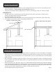
Installation 1. Align upper support frame with holes in ceiling. Mount the upper support frame to the ceiling using four “A” screws (for sheet rock only). Make sure that the upper support frame is securely fastened to the joist or support in the ceiling. Attach support frame to ceiling using anchors recommended for your type of ceiling: • Sheet rock ceiling: Attach support frame to ceiling joists or stud blockings if possible.
Installation (Continued) 9. Have a third person raise up and hold the island range hood in position, connect power plug to the 12” hanging electrical cord, and connect the duct work to the range hood. 10. Mount the hood to the lower support frame using four “B” bolts and four “C” nuts: Securely fasten two “C” nuts to two “B” bolts by reaching up from the underside of the hood. Repeat this step to secure the other side using two “C” nuts to two “B” bolts. 11.
Range Hood Operations Control Panel Layout and Buttons Configurations: Power Decrease Value Light Increase Value Blower Power Indicator Power-On Elapsed Digital Timer Blower Speed Indicator Power-Off Delay Digital Timer Light Power Indicator Power-Off Delay Timer Indicator The island canopy hood is designed to remove smoke, cooking vapors and odors from the cook top area.
Range Hood Operations (Continued) Control Panel Layout and Buttons Configurations: Power Decrease Value Light Increase Value Blower Power Indicator Power-On Elapsed Digital Timer Blower Speed Indicator Power-Off Delay Digital Timer Light Power Indicator • Power-Off Delay Timer Indicator Controls: • Adjusting the timer function: • While the blower (motor) is not running, press and hold Decrease Value button over 3 seconds to enter timer mode.
Troubleshooting 1. If the range hood or halogen light does not operate after installation: • • Check if the range hood has been plugged in, make sure that all power has been turned back ON, fused not blown and all electrical wiring are properly connected. Swap out light assembly to working ones to determine whether it is caused by defective bulbs. See Replacing the light bulbs on Page 17. 2.
Use and Care Information Operations: • • • • • Read and understand all instructions and warnings in this manual before operating the appliance. Save these instructions for future reference. Always leave safety grills and filters in place. Without these components, operating blowers could catch on to hair, fingers and loose clothing. NEVER dispose cigarette ashes, ignitable substances, or any foreign objects into blowers. NEVER leave cooking unattended.
Wiring Diagram Page 16
Maintenance SAFETY WARNING: Never put your hand into area housing the fan while the fan is operating! For optimal operation, clean range hood and all baffle/spacer/filter/grease tunnel/oil container regularly. Regular care will help preserve the appearance of the range hood. Cleaning Exterior surfaces: • Clean periodically with hot soapy water and clean cotton cloth. Do not use corrosive or abrasive detergent (e.g.
Warranty TO OBTAIN SERVICE UNDER WARRANTY: Yoou mu Y You must st pre rese sent se nt prooff of of or oriig igin inall purch chas has asee da date date te.. Plea Pl ease se provi vid ide de aann or oriig igin inall dattedd prooff of of pu p rc rchhase hase (sa salles les re rece ceiip ipt / invo invoiic ice)) in in or ordder der to to obt obtai ain in se serv rviice ice un undder der wa warr rran antty ty. One Year Parts Warranty: For one year from the date of original purchase, Euro-Kitchen, Inc.
Disclaimer Carefully inspect all items for damages before accepting delivery. note any damages on the freight bill or express receipt. request name and signature of the carrier’s agent and keep copy to support your claim. Upon acceptance of items, owner assumes responsibility for its safe arrival. Report damages to the carrier and file a claim immediately. Failure to do so may result in the denial of your claim. The carrier will furnish you with necessary forms for filing a claim.
Your Notes Page 20
Your Notes Page 21
Euro-Kitchen, Inc. 2341 Industrial Parkway West Hayward, CA 94545 Ph: 510.266.0099 Fax: 510.266.6630 http://www.euro-kitchen.