
Installation guide

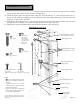


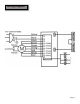

Slide up and secure
upper chimney
Slide up, hold in position
and secure lower chimney
to range hood
Secure
upper
support
frame
Insert lower
support
frame with
extensions
Adjust
support
frame
extensions
Stud
blockings
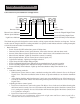
Page 10
Figure 3
Figure 4
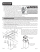
Installation
Align upper support frame with holes in ceiling. Mount 1.
the upper support frame to the ceiling using four “A”
screws (for sheet rock only). Make sure that the upper
support frame is securely fastened to the joist or support
in the ceiling. Attach support frame to ceiling using an-
chors recommended for your type of ceiling:
Sheet rock ceiling: Attach support frame to ceiling •
joists or stud blockings if possible. If ceiling joists
or stud blockings are not available, it is required to
build a supporting structure behind the sheet rock for best weight support.
Concrete ceiling: Use designated screws (not provided).•
Wood ceiling: Use at least 4” long wood screws (not provided).•
Recirculating (Non-Vented) Kit:2. If Re-Circulating Kit is not purchased, skip this step. Place the air diverter
inside upper support frame so that its 6” round hole faces downward into the lower support frame and secure
it with four “D” bolts. Be sure to let through the 12” of electrical cord hanging from the ceiling.
Position the support frame extensions at the inside corners of the support frames, adjust and mark each sup-3.
port frame extension as necessary to achieve the proper height for the range hood to be set away from the cook
top. (See Height and Clearance on Page 5 and Installation Overview on next page).
Fasten the support frame extension onto the lower support frame using four “B” bolts and “C” nuts as shown 4.
in Figure 3. Repeat this step for rest of the support frame extensions. IMPORTANT: Always use first and
second holes on the support frame extensions.
Calculate the height of the duct tube and extend approximately 6 inches longer than required, connect the up-5.
per end of the duct tube to the vent system.
Position the lower support frame with support frame extensions to the upper support frame, fasten each exten-6.
sion with four “B” bolts and “C” nuts as shown in Figure 3.
Slide the upper chimney cover over the completed 7.
support frame and fasten with two “D” bolts to the
upper support frame. (See Figure 3 for illustrations).
Slide the lower chimney cover around the lower sup-8.
port frame and around the upper chimney cover. Have
second person to hold it in position. (See Figure 4).