
User manual

Page 86 of 98
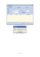
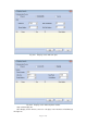
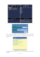
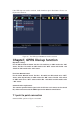
If the LED sign can not be searched, it will show that sign in Red letters. Please see
Fig.6.34 for reference.
Fig. 6.34 The LED sign QS5006 can not be searched
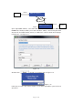
Chapte7, GPRS Dial-up function
Dip switch setting:
For the Master QS5136 board: Set the 4 bit switches on SW2 need to be “ON”
status; The No. 2 bit switch on SW3 needs to be “OFF” status and the No. 1 bit
switch on SW3 needs to be “ ON” status.
For Slaver QS5136 board:
For the Slaver QS5136 board: The No. 1 bit switch on SW2 needs to be “OFF”
status; other dip switches on SW2 need to be “ON” status. The No. 2 bit switch
on SW3 needs to be “OFF” status and the No. 1 bit switch on SW3 needs to be
“ ON” status.
Communication requirement:
The common parallel RS232 signal cable is OK. One end connect to the control
PC, anther end connect to the COM 2 port on the QS5136 control board
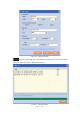
7.1 point to point connection
Connect GPRS system as Figure 7.10 shown