
User manual


00035719.DOC, Version 1.2
19/39
5.5 DMX-512 control
The wires must not come into contact with each other, otherwise
the devices will not work at all, or will not work properly.
Only use a stereo shielded cable and 3-pin XLR-plugs and connectors in order to connect the controller with
the device or one device with another.
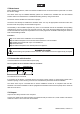
Occupation of the XLR-connection:
If you are using controllers with this occupation, you can connect the DMX-output of the controller directly
with the DMX-input of the first device in the DMX-chain. If you wish to connect DMX-controllers with other
XLR-outputs, you need to use adapter-cables.
Building a serial DMX-chain:
Connect the DMX-output of the first device in the DMX-chain with the DMX-input of the next device. Always
connect one output with the input of the next device until all devices are connected.
Caution: At the last device, the DMX-cable has to be terminated with a terminator. Solder a 120
resistor
between Signal (–) and Signal (+) into a 3-pin XLR-plug and plug it in the DMX-output of the last device.
5.6 Addressing
Each device occupies 1 or 4 channels, respectively. To ensure that the control signals are properly directed
to each device, the device requires adressing. This is to be done for every single device by changing the DIP
switches as set out in this table.
The starting address is defined as the first channel from which the device will respond to the controller.
Please make sure that you don’t have any overlapping channels in order to control each device correctly and
independently from any other device on the DMX data link. If two, three or more device are addressed
similarly, they will work similarly.
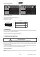
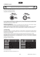
Occupation of the Dip switches:
Device1-channel1
On
Off
Startingaddress
Device number
&channels
Off
Device 2-channel2
On
Off
Device 3-channel3
On
Off
Device 4-channel4
On
Off
Device 5-channel5
On
Off
12
4
8
16
32
64
128
256
DIP-switchno.
12
3
4
5
6
7
8
9
SettingtheDMX-
startingaddress:
Device1-channels1-4
On
Off
DMX-starting
address
Projectornumber
&channels
Off
Device 2-channels5-8
On
Off
Device 3-channels9-12
On
Off
Device 4-channels13-16
On
Off
Device 5-channels17-20
On
Off
12
4
8
16
32
64
128
256
DIP-switchno.
12
3
4
5
6
7
8
9
SettingtheDMX-
startingaddress:
This device can be defined as a 4-channel switchpack (normal DMX) or as with one address for all 4
channels (DMX parallel).
Please adjust your selection via Dip switch no. 10.