
Datasheet

Product specifi cations in this catalog are subject to change without notice.Request our product specifi cations before purchase and/or use. Please use our products based on the information contained in this catalog and product specifi cations.
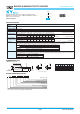
L' 15min. 4min.
φD'
φd
F±0.5
Vent
(Exceptφ5 &φ6.3)
F±0.5
Sleeve (PET : Brown)
●Newly innovative electrolyte is employed to minimize ESR
●Endurance with ripple current : 4,000 to 10,000 hours at 105℃
●Non solvent resistant type
●RoHS Compliant
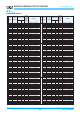
◆SPECIFICATIONS
Category
Temperature Range
Rated Voltage Range
Capacitance Tolerance
Leakage Current
Dissipation Factor
(tanδ)
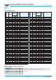
Low Temperature
Characteristics
(Max. Impedance Ratio)
Endurance
Shelf Life
Items
-
40 to +105℃
6.3 to 100V
dc
±20% (M)
I
=
0.01CV or 3µA, whichever is greater.
Where, I : Max. leakage current (µA), C : Nominal capacitance (µF), V : Rated voltage (V)
Rated voltage (V
dc)
tanδ (Max.)
When nominal capacitance exceeds 1,000µF, add 0.02 to the value above for each 1,000µF increase.
Rated voltage (V
dc)
Z(
-
25℃)/Z(
+
20℃)
Z(
-
40℃)/Z(
+
20℃)
The following specifications shall be satisfied when the capacitors are restored to 20℃ after subjected to DC voltage with the rated
ripple current is applied (the peak voltage shall not exceed the rated voltage) for the specified period of time at 105℃.
Time
φ5 & 6.3 : 4,000hours φ8 & 10 : 6,000hours φ12.5 to 18 : 8,000hours
φ5 & 6.3 : 5,000hours φ8 & 10 : 7,000hours φ12.5 to 18 : 10,000hours
Capacitance change ≦±25% of the initial value
D.F. (tanδ) ≦200% of the initial specified value
Leakage current ≦The initial specified value
The following specifications shall be satisfied when the capacitors are restored to 20℃ after exposing them for 500 hours at 105℃ without
voltage applied. Before the measurement, the capacitor shall be preconditioned by applying voltage according to Item 4.1 of JIS C 5101-4.
Capacitance change ≦±25% of the initial value
≦200% of the initial specified value
Leakage current ≦The initial specified value
Characteristics
(at 20℃, 120Hz)
(at 20℃ after 2 minutes)
(at 20℃, 120Hz)
(at 120Hz)
6.3V
4
8
10V
3
6
16V
2
4
25V
2
3
35V
2
3
50V
2
3
6.3V
0.22
10V
0.19
16V
0.16
25V
0.14
35V
0.12
50V
0.10
63V
2
3
63V
0.09
80V
2
3
80V
0.09
100V
2
3
100V
0.08
6.3 to 10V
dc
16 to 100Vdc
◆DIMENSIONS [mm]
◆PART NUMBERING SYSTEM
5
0.5
2.0
φD
φd
F
φD'
L'
6.3
0.5
2.5
8
0.6
3.5
12.5
0.6
5.0
16
0.8
7.5
18
0.8
7.5
10
0.6
5.0
φD+0.5max.
L+1.5max.
(φ5 to φ10)
Gas escape end seal
KY
Lower Z
Lower Z
KZE
KZH
●Terminal Code : E
Supplement code
Size code
Capacitance tolerance code
Capacitance code (ex. 1.0µF:1R0,10µF:100,100µF:101)
Lead forming·taping code
Terminal code
Voltage code (ex. 6.3V:6R3,50V:500)
Series code
Category
E KY
-
E M
1342 6 7 8 9 10 1312518171611 1514
Please refer to "Product code guide (radial lead type)"
D.F. (tanδ)
(φ12.5 to φ18)
MINIATURE ALUMINUM ELECTROLYTIC CAPACITORS
Low impedance, 105℃
CAT. No. E1001L(1/3)