
Datasheet

Product specifi cations in this catalog are subject to change without notice.Request our product specifi cations before purchase and/or use. Please use our products based on the information contained in this catalog and product specifi cations.
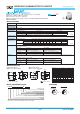
SURFACE MOUNT ALUMINUM ELECTROLYTIC CAPACITORS
Downsized, 105℃
●Rated voltage range : 6.3 to 450V, capacitance range : 1.0 to 6,800μF
●Endurance : 1,000 to 2,000 hours at 105℃
●Case size range :φ4×5.2L to φ18×21.5L
●Solvent resistant type except 100 to 450Vdc (see PRECAUTIONS AND GUIDELINES)
●RoHS Compliant
◆SPECIFICATIONS
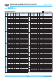
◆DIMENSIONS [mm]
(20℃, 120Hz)
(20℃)
(20℃, 120Hz)
(120Hz)
≦±20% of the initial value
≦200% of the initial specified value
≦The initial specified value
2,000 hours
≦±20% of the initial value
≦200% of the initial specified value
≦The initial specified value
-40 to +105℃
6.3 to 450V
dc
±20%(M)
Rated voltage(V
dc)
D55 to JA0 I=0.01CV or 3μA, whichever is greater (2 minutes)
KE0 to MN0 I=0.03CV or 4μA, whichever is greater (1 minute) I=0.04CV+100μA (1minute)
Where, I : Max. leakage current (μA), C : Nominal capacitance (μF), V : Rated voltage (V)
See STANDARD RATINGS
Rated voltage (V
dc)
Z(-25℃)/Z(+20℃)
Z(-40℃)/Z(+20℃)
Z(-25℃)/Z(+20℃)
Z(-40℃)/Z(+20℃)
The following specifications shall be satisfied when the capacitors are restored to 20℃ after the rated voltage is applied for the specified
period of time at 105℃.
Size code
Time 1,000 hours
Capacitance change ≦±30% of the initial value
D.F. (tanδ) ≦300% of the initial specified value
Leakage current ≦The initial specified value
The following specifications shall be satisfied when the capacitors are restored to 20℃ after exposing them for 1,000 hours (500 hours
for B55 to F80 size) at 105℃ without voltage applied. Before the measurement, the capacitor shall be preconditioned by applying voltage
according to Item 4.1 of JIS C 5101-4.
Size code
Capacitance change ≦±25% of the initial value
D.F. (tanδ) ≦200% of the initial specified value
Leakage current ≦The initial specified value
6.3V
4
12
5
10
10V
3
8
4
8
16V
2
6
3
6
25V
2
4
2
4
35V
2
3
2
3
50V
2
3
2
3
63V
2
3
2
3
160 to 250V
-
-
3
6
400 to 450V
-
-
6
10
100V
3
4
2
3
160 to 450V6.3 to 100V
-
D55 to JA0
KE0 to MN0
HA0 to MN0D55 to F80
D55 to F80
HA0 to MN0
Category
Temperature Range
Rated Voltage Range
Capacitance Tolerance
Leakage Current
Dissipation Factor
(tanδ)
Low Temperature
Characteristics
(Max. Impedance Ratio)
Endurance
Shelf Life
CharacteristicsItems
φD
±
0.5
L
±
0.3 (Note)
0.3max.
A
±
0.2
W
C
±
0.2
B
±
0.2
P
Note : L±0.5 for HA0 to MN0
φD
±
0.5
B
±
0.2
L
±
0.5
0.3max.
A
±
0.2
W
C
±
0.2
P
: Dummy terminals
◆PART NUMBERING SYSTEM
Longer life
MVE
MVL
MVJ
◆MARKING
7hE
22
16V
Ex)16V22μF
MVE
0V
1000
25V
Ex)25V1,000μF
D55 to JA0 KE0 to MN0
Size code
D55
E55
F55
F80
HA0
JA0
KE0
KG5
LH0
LN0
MH0
MN0
D
4
5
6.3
6.3
8
10
12.5
12.5
16
16
18
18
L
5.2
5.2
5.2
7.7
10.0
10.0
13.5
16.0
16.5
21.5
16.5
21.5
A
4.3
5.3
6.6
6.6
8.3
10.3
13.0
13.0
17.0
17.0
19.0
19.0
B
4.3
5.3
6.6
6.6
8.3
10.3
13.0
13.0
17.0
17.0
19.0
19.0
C
5.1
5.9
7.2
7.2
9.0
11.0
13.7
13.7
18.0
18.0
20.0
20.0
W
0.5 to 0.8
0.5 to 0.8
0.5 to 0.8
0.5 to 0.8
0.7 to 1.1
0.7 to 1.1
1.0 to 1.3
1.0 to 1.3
1.0 to 1.3
1.0 to 1.3
1.0 to 1.3
1.0 to 1.3
P
1.0
1.4
1.9
1.9
3.1
4.5
4.2
4.2
6.5
6.5
6.5
6.5
●Terminal Code : A
●Size code : D55 to MN0
●Terminal Code : G
●Size code : LH0 to MN0
Supplement code
Size code
Capacitance tolerance code
Capacitance code (ex. 4.7
μF:4R7,100μF:101)
Taping·Tray code
Terminal code (A, G)
Voltage code (ex. 6.3V:6R3,100V:101,450V:451)
Series code
Category
E M V E A A A A A A A A A A A A NM
1342 678910 31215 817161111514
Please refer to "Product code guide (surface mount type)"
CAT. No. E1001L(1/2)