TM Multi-Cell PRI Gateway ISDN PRI to GSM Gateway Version 01.
For additional assistance please contact us: Support Team Eurotech Communication Ltd. P.O. Box 621 Z.H.R. Industrial Park Rosh Pina, 12000, ISRAEL Tel: +972-4-680-1080 Fax: +972-4-680-1081 Email: Support@Eurotech-Communication.com Web: www.Eurotech-Communication.com Usage Warnings 1) High voltage transients, surges, and other power irregularities can cause extensive damage. It is the user's responsibility to provide a power protection system.
Dear Customer, We thank you for purchasing our GSM Multi Cell to ISDN PRI Gateways. The information in this manual does not constitute a warranty of performance, although the information has been compiled and checked for accuracy by Eurotech Communication Ltd. All our products are developed and produced by experienced engineers, who aspire to achieve customer satisfaction, utility value and reliability of products.
Table of Content Getting Started ..................................................................................................................................................... 5 Check your package Items .................................................................................................................................. 8 The ISDN PRI GSM Gateway Solution Overview...................................................................................................
Getting Started Eurotech Communication team is glad you have chosen to use the Eurotech s Multi-Cell PR gateway for your needs, we will do our best to make your installation efforts as well as day-to-day configuration and monitoring tasks be pleasant tasks as possible. We wish you a smooth operation while greatly saving your office mobile phone calls.
• Optional - Setting the TCP/IP connections If you wish to operate the management application for system management via internet connection the proper TCP/IP settings should be performed. Refer to Chapter 10: TCP/IP Setting . • Optional Managing the system via IP connection In order to manage, configure and monitor the system via IP the system TCP/IP connections, the Ethernet cables and the PRI Management MS-Windows application should be properly installed and configured. Refer to Chapter 3.
For getting the most updated Product Info on the Web Refer to http://www.eurotech-communication.com At menu: Cellular Gateways At sub menu: PRI E1/T1 GSM or CDMA (note: CDMA capabilities not supported in your package) Having Your feedback Please let us know your feedback and enhancement ideas to improve the product to your best value. Email: Support@Eurotech-Communication.
Check your package Items Please verify your package contains the following components (some were ordered specific) before installation: • Main Hardware Device - The Multi-Cell PRI Gateway • 110/220V Power supply cable • Software Installation CD - Installation kit of the PRI Management MS-Windows Application, this User Manual file and additional auxiliary utilities.
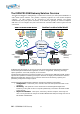
The ISDN PRI GSM Gateway Solution Overview The Multi-Cell ISDN PRI to GSM gateway is a device that connects your office phones DIRECTLY to GSM cellular phone networks. This gateway completely bypasses the local landline telephone company. 30 office phones can be connected to each Multi-Cell Gateway and operate simultaneously. Each port (phone connection) in the "Multi-Cell" gateway can hold four Cellphone SIM cards.
Chapter 1: Connecting the Cables You have several cables to connect to the Multi-Cell PRI Gateway. Some are mandatory and some are optional based on the specific use case. Basic Connections • Power Cable 110/220V - The power cable is supplied and should cover all main voltage electricity services in the world. However you should check the plug supplied with the socket where you installing the system. Connect a 120 V (North America), or 240 V (Europe) power supply cable to the Multi-Cell gateway.
and make the proper configuration according to your needs following the Management Application guidelines in the following chapters. Additional cables used as follows: o o RJ-45 ISDN E1 Cross connect cable Used in the same case as the regular ISDN E1 cable depending on the ISDN settings. RJ-45 Ethernet cross connect cable For direct IP connection to a PC in-order to set the initial IP settings of the MultiCell Gateway system.
Chapter 2: Installing the Manager Application Before operation, configuration settings must be made to the gateway. Configuration is done in an auxiliary computer with the PRI Management MS-Windows Application provided for MS-Windows operating system. Install the Multi-Cell Manager Application into an MS-Windows PC 1. Insert the Multi-Cell compact disk into the CD drive of the configuration computer. 2. In Windows Explorer, navigate to in the installation CD drive. 3.
4. Click Next. 5. The Setup Type window will open. 6. Select Complete and click next. The Begin Installation window will open. 7. Click Install. The Multi-Cell Manager application installs itself. Wait all steps till a completion message will appear.
PRI – GSM Multi-Cell Gateway 14
Chapter 3: Basic configurations with the management application Launch the Manager Application and Define the Type of Connection Between the management PC and the Multi-Cell system After installing the manager application, launch it and define the Type of Connection between the Auxiliary Computer and the Multi-Cell as described below. 1. Launch the PRI Manager by pressing on your computer desktop, or by pressing: Start > Programs > EuroTech Communications > PRI Manager. The PRI Manager window opens.
Chapter 3.1: Management via RS-232 serial connection Connect the RS-232 cable following the, from an available communication port in the computer to the Com socket in the back of the Multi-Cell. This is the default setting. If you are using this type of connection, select Com Port in the bottom frame of the window. In the selection Pull Down menu, select the computer Com Port you are using for your RS-232 cable connection with the Multi-Cell PRI Gateway.
Chapter 3.2: Management via Internet connection TCP/IP Internet connection enabled via the NET socket (RJ-45) on the Multi-Cell PRI Gateway, in the front of the Multi-Cell. Refer to Chapter 1: Connecting the Cables for the cable connection task. For TCP/IP settings of the Multi-Cell PRI Gateway refer to Chapter 10: TCP/IP Setting . 1. If you are using Internet connection for management, select TCP/IP in the bottom frame of the window.
2. Press button. The System window will open. 3. Press .button. The system is set for TCP/IP communication between the auxiliary PC and the Multi-Cell unit.
Chapter 4: Configuration - Defining Groups of Ports The Multi-Cell PRI unit is a gateway for 30 telephones. Telephones may be divided into groups. For example, each department in your office may have different call patterns. Each port represents one telephone. Define setting for group of ports as follows. 1. Press on button on the Manager Menu bar. The Groups window will open.
2. Press [Create Group] button. A new group appears at the bottom of the Port list. 3. Type a name for the new group and click outside the selected area. A group can be renamed by selecting it and pressing [Rename] button. 4. Define the ports in each group: a. Select a port b. Press [Move to Group] button. The Select Group window opens c. Select the desired group of the port. 5. When finished defining groups, press [Save Groups] button to send the group configuration to the Multi-Cell unit.
Chapter 5: Configuration - Port and SIM This chapter details port dial settings, as well as time tables and channel locks for SIMs. Chapter 5.1: Define Dial Settings for Each Port Press [ Main PRI] button to define dial settings for each port. The Port Setting window opens. To define port dial settings, click a port and proceed as described on the following pages. Select a caller identification option in the Caller ID list: • To enable the GSM network to set caller ID standards, select By Network .
Chapter 5.2: Define Phone numbers Type of Dispatch Select the mode in which telephone numbers are dispatched to the GSM network. To dispatch phone numbers manually, in the Send Complete list, select HASH mode. In this mode, after the user has dialed all digits of a phone number, press to send the phone numbe. To dispatch phone numbers automatically, in the Send Complete list, select OMIT. Then set three additional parameters: a. Length of phone numbers that will be dialed from the port within range. i.
Chapter 5.3: Configuration SIM Card Settings To define settings for a SIM, click a SIM icon. The SIM Setting window opens. Define SIM Specifications Enter SIM specifications: 1. 2. 3. 4. Enter a pre-dialing number for the specific SIM. Enter the PIN code of the SIM in the PIN CODE box. Select a caller identification option in the Caller ID list: • • • To enable the GSM network to set caller ID standards, select Network. To enable identification of the SIM, select CLIR Suppression.
Set the time passed since SIM begun to be Active Click the Time table tab. The timetable settings will appear: In the Time Table tab, define hours, and days, that the SIM is active. Days can be divided in up to four intervals. 1. Select an interval. 2. Enter the hours of the interval. 3. Select days that this interval will be activated. Select days of deactivation in the row Don not use timetables. Define type of Channel Lock To define the type of channel lock, click the BCCH Lock tab.
Chapter 6: Configuration - ISDN Connection Settings This chapter details ISDN settings starting with overview of the ISDN card in the Multi-Cell PRI gateway system and guiding for proper configuration per your needs. Chapter 6.1: Overview of the ISDN Card Each Multi-Cell gateway has a master Printed Circuit Board( PCB). The ISDN card is a small PCB mounted on the master PCB. The ISDN card is between ports in the Multi-Cell and the switching unit.
EEPROM containing ISM software. Enter the ISM version in the ISM version box. 3. Set Network access as NT, (set the switching unit as TE). 4. Define the Master/Slave status in the Synchronization box. It is preferable to define the Multi-Cell unit as the Master, and the switching unit as the slave. 5. In the Incoming Calls box, select the interface of incoming calls (from the switching unit to the ISDN card), Overlap (pulse) or In Block (packet) in conformity with the setting in the switching unit.
Chapter 6.2: Configuration - ISDN B-Channel-Port Association This chapter explains the assigning of B-channels to in-house phones and the allocation of calls to Multi-Cell ports. Chapter 6.2.1: Assigning B-channels to In-house Numbers Assigned B-channels to ports in the switching unit as follows: 1. Press to open the B-Channel/Port window. 2. Press the B-Ch Numbers tab. 3. Mark the B-Ch setting, in order to activate all B-channels. Unmark a B-channel to deactivate it.
GSM Cellphone PSTN Phone RJ-11 Ring signal parameters: Incoming calls, from PBX to ISDN card: minimum digits (Example 050-787-4444= 10 digits) SIM Device GSM Module PSTN Switching E1 line Eurotech’s GSM Multi-Cell PRI Gateway "Outgoing" calls, from ISDN card to PBX: maximum digits (example 6001 = 4 digits) The Outgoing Number column refers to calls from the Multi-Cell, to a phone extending from the switching unit, as illustrated above. 4.
Chapter 6.2.2: Assigning Ports and Defining Prefixes This section explains how to assign a port allocation mode for the Multi-Cell. A port allocation mode determines the manner in which a port is selected when placing a call from a phone extending from the switching unit, to a GSM network phone. 1. In the B-Channel/Port window press the Ports/Prefixes tab. The default alignment of Bchannels to ports is displayed. B-channels can be reassigned to different ports by dragging them.
3. In the Allocation frame, select the type of Allocation Mode desired. • Static allocation: Each B-channels is permanently assigned to a port (GSM module), as they are aligned in this tab. • Cyclic allocation: As each phone call is made, the next available port (GSM module) is assigned to the B-channel. • Random allocation: Any available port (GSM module) is assigned to the B-channel.
Chapter 8: Monitoring Calls This chapter explains how to monitor calls and review reports. To monitor calls press . The monitor screen will open. Press to hide or view B-channel status, as well as the status of the following connections: • • • Comport Network ISDN A red LED indicates there is no connection. A yellow LED indicates there is a connection, but no data transfer. A green LED indicates transfer of data.
Quality of Reception GSM Network BCCH Number Time Limit on SIM Status button Port and B-Channel SIM connection status Network connection status Choose the Get Cell Information at the Status Button.
Legend: LAC Location Area Code.
Chapter 9: Generating Call Reports Press to review the call report. This screen defines the parameters for a successful or unsuccessful call. The system may store 30,000 calls with full reports for 30 channels without PC! The system may export these reports to MS-Access, CSV (MS-Excel) or standard XML format. The export of call records will be time based.
Chapter 10: TCP/IP Setting TCP/IP settings task list: 1. Disconnect the COM cable from the Multi-Cell system. 2. Install RJ-45 cable to the Management PC connected to the Multi-Cell network. 3. Execute to the same LAN Network Enabler Administrator program, provided on the installation CD at the directory LAN Tools ; 4. If your IP addresses are between 192.168.0.1 and 192.168.0.255, connect the Multi-Cell to LAN access point and continue to step 6, if other, then proceed to the next step; 5.
11. Check the Modify check box above the IP Address and enter the desired IP; 12.
Chapter 11: Operational test From a PSTN Office phone attached to a PBX/ VoIP Gateway try make a call to defined GSM Cellphone in the GSM network around. In case of a failure to do so verify the following: • • • The PRI is configured properly to your PBX / VoIP gateway The connection is not properly attached or disconnected The cable itself is malfunction If your verifications did not yet any results, It might be that the GSM module is not compatible with the GSM network around.
Press the Monitor window button, it will open showing a pull down set of physical port numbers. Choose the wanted port, for your testing. Enter the desired phone number in the field named Enter the dial number below and press the button. In few seconds the GSM phone shall ring and after call accepted, check the voice call operating properly, between the attached RJ-11 handset and the called GSM mobile phone.
Chapter 12: Troubleshooting and known issues The following are main debugging tools which are very useful to overcome connection problems: • The RJ-11 handset, • The PRM Manager Debug Window. Chapter 12.1: The Handset 1. To use a handset, press button. The Handset window will open attached to the Multi-Cell, added to 101. 2. In the Username and password fields, enter "admin in lower case. 3. Press Logon button. 4.
Chapter 12.2: The Management Appluaction Debug Window 1. To open the Debug screen, press . The Debug window opens. 2. Use this only when in contact with a support technician.
There are several common problems and solution we have collected to share with you as follow: Q.: I m trying to connect to the MultiCell via LAN, with the PRI Management application, but I keep getting the error message. How to resolve? A.: Unhook the COM cable from the MultiCell and reboot it. If reboot is unwanted, connect to the MultiCell via COM cable with PRI Management application, go to the System screen and perform actions, described there: 1. Press . The System window will open. 2. Press .
Q.: I ve got too many cables with the MultiCell, which part of I do not know how to use them. Any advise? A.: There are five connection cables and one power cable, supplied with the Multi-Cell PRI Gateway package: • RS232/RJ11 cable for connecting the MultiCell to an auxiliary computer (PC). • Two straight cables, one for the Ethernet LAN connection and the other for the ISDN connection (in case the MultiCell is set to TE Network Access).
Q.: How can I check if my MultiCell s firmware is up-to-date? A.: Connect to the MultiCell, using the PRI management application. Go to the Debug screen. Check the Enable Debug checkbox, uncheck the Enable filter checkbox. At the field, near the SEND button, enter R_SID11 and press enter. Two rows will be the feedback. At the same field enter R_SYS and press enter. One row of feedback will be shown. Uncheck the Enable Debug checkbox.