31 VIPER / VIPER-Lite PXA255 RISC based PC/104 Single Board Computer Technical Manual
VIPER Technical Manual Definitions Eurotech is the trading name for Eurotech Ltd. Disclaimer The information in this manual has been carefully checked and is believed to be accurate. Eurotech assumes no responsibility for any infringements of patents or other rights of third parties, which may result from its use. Eurotech assumes no responsibility for any inaccuracies that may be contained in this document. Eurotech makes no commitment to update or keep current the information contained in this manual.
VIPER Technical Manual Contents Contents Introduction ........................................................................................................................................4 VIPER ‘at a glance’................................................................................................................5 VIPER-Lite ‘at a glance’ .........................................................................................................6 VIPER features ......................................
VIPER Technical Manual Introduction Introduction The VIPER is an ultra low power, PC/104 compatible, single board computer available in two standard variants: • VIPER, based on the 400MHz PXA255 XScale processor. • VIPER-Lite, based on the 200MHz PXA255 XScale processor.
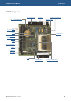
VIPER Technical Manual Introduction VIPER ‘at a glance’ Five Serial Ports Jumpers Audio – In/Out/MIC/AMP 10/100BaseTX Ethernet Ethernet LEDs Power (inc reset input) Battery TPM Tamper (optional) 400MHz PXA255 processor 8/16-bit PC/104 interface JTAG Intel StrataFLASH Jumpers USB Client Digital I/O USB TFT/STN panel © 2007 Eurotech Ltd Issue E CompactFLASH (CF+) 5
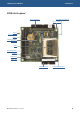
VIPER Technical Manual Introduction VIPER-Lite ‘at a glance’ Three Serial Ports 10/100BaseTX Ethernet Ethernet LEDs Power (inc reset input) Battery 200MHz PXA255 processor JTAG Intel StrataFLASH Jumpers USB Client Digital I/O TFT/STN panel © 2007 Eurotech Ltd Issue E CompactFLASH (CF+) 6
VIPER Technical Manual Introduction VIPER features Microprocessor • PXA255 400MHz (VIPER) or 200MHz (VIPER-Lite) RISC processor. • 32K data cache, 32K instruction cache, 2K mini data cache. • 64MB un-buffered 3.3V SDRAM. • Up to 16/32MB Intel StrataFLASH (with FLASH access LED). • 1MB bootloader FLASH EPROM (with FLASH access LED). • 256KB SRAM (battery backed). • Type I/II CompactFLASH (CF+) socket. • TFT/STN (3.3V or 5V) flat panel graphics controller. • Up to 640X480 resolution.
VIPER Technical Manual Introduction Network support • • SMSC LAN91C111 10/100BaseTX Ethernet controller. One 10/100BaseTX NIC port. Trusted Platform Module (TPM) [optional] VL • Atmel AT97SC3201 TPM security, with full TCG/TCPA V1.1b compatibility. VL • Includes crypto accelerator capable of computing a 1024-bit RSA signature in 100ms. • Battery backed RTC. • ± 1minute/month accuracy, at 25°C. • Adjustable timeout of 271ns to 19 minutes 25 seconds.
VIPER Technical Manual Introduction VIPER support products The VIPER supports the following products: • VIPER-UPS (Uninterruptible Power Supply) The VIPER-UPS serves as a 5V DC power supply and battery back up system for the VIPER. The UPS accepts between 10 – 36 VDC (10-25VAC) input and generates the +5V supply for the VIPER.
VIPER Technical Manual Introduction • CYCLOPS The CYCLOPS is a rugged VIPER display terminal. The enclosure can be configured to suit a complete range of embedded applications with LCD display and touchscreen. • VIPER-ICE (Industrial Compact Enclosure) development kits The VIPER-ICE is a simple low cost aluminium enclosure, which provides easy connection to all on board features.
VIPER Technical Manual • Introduction Wind River VxWorks 5.5 development kit Features of this kit are: - 400MHz PXA255 processor with 64MB DRAM & 32MB Flash memory. - VxWorks BSP for Tornado 2.2.1/VxWorks 5.5.1/Wind ML 3.0.2. - Pre-configured build of VxWorks, tailored specifically for the VIPER, pre-loaded into the 32MB Flash. - Rugged enclosure with optional NEC Q-VGA TFT colour display and analogue touchscreen.
VIPER Technical Manual Introduction Product handling and environmental compliance Anti-static handling This board contains CMOS devices that could be damaged in the event of static electricity discharged through them. At all times, please observe anti-static precautions when handling the board. This includes storing the board in appropriate anti-static packaging and wearing a wrist strap when handling the board.
VIPER Technical Manual Introduction Conventions Symbols The following symbols are used in this guide: Symbol Explanation Note - information that requires your attention. Tip - a handy hint that may provide a useful alternative or save time. Caution - proceeding with a course of action may damage your equipment or result in loss of data. VL Indicates that a feature is not available on the standard VIPER-Lite configuration.
VIPER Technical Manual Introduction Tables With tables such as that shown below, the white cells show information relevant to the subject being discussed. Grey cells are not relevant in the current context.
VIPER Technical Manual Getting started Getting started Depending on the development kit purchased, a Quickstart Manual is provided for Windows CE, embedded Linux or VxWorks to enable users to set-up and start using the board. Please read the relevant manual and follow the steps defining the set-up of the board. Once you have completed this task you will have a working VIPER system and can start adding further peripherals enabling development to begin.
VIPER Technical Manual Getting started Using the audio features There are four audio interfaces supported on the VIPER: amp out, line out, line in and microphone. The line in, line out and amp interfaces support stereo signals and the microphone provides a mono input. The amplified output is suitable for driving an 8Ω load with a maximum power output of 250mW per channel. Connections are routed to PL6 - see the sections Audio (page 56) and PL6 – Audio connector (page 91) for further details.
VIPER Technical Manual Getting started Using the PC/104 expansion bus VL PC/104 modules can be used with the VIPER to add extra functionality to the system. This interface supports 8/16 bit ISA bus style peripherals. Eurotech Ltd has a wide range of PC/104 modules, which are compatible with the VIPER. These include modules for digital I/O, analogue I/O, motion control, CAN bus, serial interfaces, etc.
VIPER Technical Manual Detailed hardware description Detailed hardware description The following section provides a detailed description of the functions provided by the VIPER. This information may be required during development after you have started adding extra peripherals or are starting to use some of the embedded features. VIPER block diagram The diagram below illustrates the functional organization of the VIPER PC/104 SBC.
VIPER Technical Manual Detailed hardware description VIPER address map VL VL VL PXA255 chip select Physical address Bus/register width Description - - Reserved SDCS0 0xA0000000 – 0xA3FFFFFC 32-bit SDRAM, IC2&3 - 0x4C000000 – 0x9FFFFFFF - Reserved NA 0x48000000 – 0x4BFFFFFF 32-bit Memory Control Registers1 NA 0x44000000 – 0x47FFFFFF 32-bit LCD Control Registers1 NA 0x40000000 – 0x43FFFFFF 32-bit PXA255 Peripherals1 - 0x3C200400 – 0x3FFFFFFF - Reserved NA 0x3C000000 – 0x3C1F
VIPER Technical Manual Detailed hardware description Translations made by the MMU For details of translations made by the MMU by Redboot for embedded Linux, please refer to the VIPER Embedded Linux AEL Technical Manual. For details of translations made by the MMU by Redboot for VxWorks, please refer to the VIPER VxWorks Quickstart and Technical Manual. For details of translations made by the MMU for Windows CE, please check the Windows CE documentation for more information about memory mapping.
VIPER Technical Manual Detailed hardware description PXA255 processor The PXA255 is a low power ARM (version 5TE) instruction set compliant RISC processor. The PXA255 does not include a floating-point unit. The device does, however, contain a DSP co-processor to enhance multimedia applications. The VIPER is fitted with a 400MHz PXA255 variant and the VIPER-Lite is fitted with a 200MHz PXA255 variant. The clock source for these is a 3.
VIPER Technical Manual Detailed hardware description PXA255 GPIO pin assignments The following table summarizes the use of the 85 PXA255 GPIO pins, their direction, alternate function and active level. For embedded Linux the GPIO pins are setup by Redboot. Under VxWorks and Windows CE, they are setup by the OS and not by the bootloader. Key: AF Dir Active Sleep VL Alternate function. Pin direction. Function active level or edge. Pin state during sleep mode (all Hi-Z states are to ‘1’ during sleep).
VIPER Technical Manual GPIO No AF Signal name 14 0 Detailed hardware description Dir FLASH_ STATUSInput Active Sleep Function See section… NA Input Bootloader FLASH Status, Ready / nBusy Interrupt assignments (page 30) and FLASH memory/silicon disk (page 27) 49H 305H 306H 307H 15 2 CS1 Output Low Hi-Z Chip Select 1 VIPER address map (page 19) 308H 309H 16 17 2 2 PWM0 PWM1 0 Output See inverter datasheet Backlight Brightness On/Off or variable if PWM Output NA STN Bias 0 L
VIPER Technical Manual Detailed hardware description GPIO No AF Signal name Dir Active Sleep Function 34 1 RXD1 Input NA Input COM1 Receive Data 35 1 CTS1 Input NA Input COM1 Clear To Send 36 1 DCD1 Input NA Input COM1 Data Carrier Detect 37 1 DSR1 Input NA Input COM1 Data Sender Ready 38 1 RI1 Input NA Input COM1 Ring Indicator 39 2 TXD1 Output NA 0 COM1 Transmit Data 40 2 DTR1 Output NA 0 COM1 Data Terminal Ready See section… Serial COMs ports (page 6
VIPER Technical Manual Detailed hardware description GPIO No AF Signal name Dir 58 2 LCD_D0 59 2 60 Active Sleep Function Output NA 0 LCD Data Bit 0 LCD_D1 Output NA 0 LCD Data Bit 1 2 LCD_D2 Output NA 0 LCD Data Bit 2 61 2 LCD_D3 Output NA 0 LCD Data Bit 3 62 2 LCD_D4 Output NA 0 LCD Data Bit 4 63 2 LCD_D5 Output NA 0 LCD Data Bit 5 64 2 LCD_D6 Output NA 0 LCD Data Bit 6 65 2 LCD_D7 Output NA 0 LCD Data Bit 7 66 2 LCD_D8 Output NA 0 LCD Data Bit 8
VIPER Technical Manual Detailed hardware description Real time clock There are two RTCs on the VIPER. Under embedded Linux and VxWorks the internal RTC of the PXA255 should only be used for power management events, and an external Dallas DS1338 RTC should be used to keep the time and date. Under Windows CE the time and date stamps are copied from the external RTC to the internal RTC of the PXA255, to run the RTC internally. The accuracy of the DS1338 RTC is based on the operation of the 32.
VIPER Technical Manual Detailed hardware description Memory The VIPER has four types of memory fitted: VL • 1MB of bootloader FLASH containing Redboot to boot embedded Linux or VxWorks, or Eboot to boot Windows CE. • A resident FLASH disk containing the OS and application images. • SDRAM for system memory. • 256KB Static RAM (SRAM). A 1MB Bottom Boot FLASH EPROM device, arranged as 512Kbit x 16, is used as the bootloader FLASH.
VIPER Technical Manual Detailed hardware description Static RAM VL The VIPER has a 256KB SRAM device fitted, arranged as 256Kbit x 8-bits. Access to the device is on 16-bit boundaries; whereby the least significant byte is the SRAM data and the 8-bits of the most significant byte are don’t care bits. The reason for this is that the PXA255 is not designed to interface to 8-bit peripherals.
VIPER Technical Manual Detailed hardware description Interrupt configuration and reset register [ICR] Byte lane Most Significant Byte Bit Least Significant Byte 15 14 13 12 11 10 9 8 7 6 5 4 3 2 Field - - - - - - - - - - - - CF_ RST R_DIS Reset X X X X X X X X 0 0 0 0 0 0 R/W - - - - - - - - Address R 1 0 AUTO_ RETRIG CLR 0 0 R/W 0x14100002 ICR Bit Functions Bit Name 0 Function 0 No interrupt retrigger (embedded Linux and VxWorks).
VIPER Technical Manual Detailed hardware description Interrupt assignments Internal interrupts For details on the PXA255 interrupt controller and internal peripheral interrupts please see the PXA255 Developer’s Manual on the Development Kit CD. External interrupts The following table lists the PXA255 signal pins used for generating external interrupts.
VIPER Technical Manual Detailed hardware description PC/104 interrupt register [PC104I1] Byte lane Bit Most Significant Byte Least Significant Byte 15 14 13 12 11 10 9 8 Field - - - - - - - - Reset X X X X X X X X R/W - - - - - - - - Address 7 6 5 4 3 2 1 0 IRQ12 IRQ11 IRQ10 IRQ7 IRQ6 IRQ5 IRQ4 IRQ3 0 0 0 0 0 0 0 0 1 0 R/W 0x14100000 PC/104 interrupt register [PC104I2] (not available under Windows CE) Byte lane Bit Most Significant Byte Least S
VIPER Technical Manual Detailed hardware description ICR Bit Functions Bit Name 0 Value Function 0 No interrupt retrigger (embedded Linux and VxWorks) 1 Interrupt retrigger (Windows CE) 0 No auto clear interrupt / Toggle GPIO1 on new interrupt (embedded Linux and VxWorks) 1 Auto clear interrupt / pulse low for 1.
VIPER Technical Manual Detailed hardware description PC/104 interrupts under Windows CE Write 0x2 to the ICR Register so that the first PC/104 interrupt source causes the PXA255 PC/104 interrupt pin GPIO1 to receive a low to high transition. When the first PC/104 interrupt occurs the Interrupt service routine will start polling through the PC/104 interrupt sources in the PC104I1 register. The first bit it sees set to a ‘1’, sets a semaphore to make a program run to service the corresponding interrupt.
VIPER Technical Manual Detailed hardware description Flat panel display support The PXA255 processor contains an integrated LCD display controller that permits 1, 2 and 4-bit grey-scale, and 8 or 16-bit colour pixels. A 256-byte palette RAM provides flexible colour mapping capabilities. The LCD display controller supports active (TFT) and passive (STN) LCD displays.
VIPER Technical Manual Detailed hardware description TFT panel data bit mapping to the VIPER Panel data bus bit 18-bit TFT 12-bit TFT 9-bit TFT FPD 15 R5 R3 R2 FPD 14 R4 R2 R1 FPD 13 R3 R1 R0 FPD 12 R2 R0 - FPD 11 R1 - - GND R0 - - FPD 10 G5 G3 G2 FPD 9 G4 G2 G1 FPD 8 G3 G1 G0 FPD 7 G2 G0 - FPD 6 G1 - - FPD 5 G0 - - FPD 4 B5 B3 B2 FPD 3 B4 B2 B1 FPD 2 B3 B1 B0 FPD 1 B2 B0 - FPD 0 B1 - - GND B0 - - The PXA255 cannot directly interf
VIPER Technical Manual Detailed hardware description STN panel data bit mapping to the VIPER Panel data bus bit Dual scan colour STN Single scan colour STN Dual scan mono STN FPD 15 DL7(G) - - FPD 14 DL6(R) - - FPD 13 DL5(B) - - FPD 12 DL4(G) - - FPD 11 DL3(R) - - FPD 10 DL2(B) - - FPD 9 DL1(G) - - FPD 8 DL0(R) - - FPD 7 DU7(G) D7(G) DL3 FPD 6 DU6(R) D6(R) DL2 FPD 5 DU5(B) D5(B) DL1 FPD 4 DU4(G) D4(G) DL0 FPD 3 DU3(R) D3(R) DU3 FPD 2 DU2(B) D2(B) D
VIPER Technical Manual Detailed hardware description Typically the power up sequence is as follows (please check the datasheet for the particular panel in use): 1 Enable display VCC. 2 Enable flat panel interface. 3 Enable backlight. Power down is in reverse order. LCD backlight enable The PXA255 GPIO9 pin controls the LCD inverter supply voltage for the backlight. When GPIO9 is set to logic ‘1’, the backlight supply BLKSAFE is supplied with 5V (turned on).
VIPER Technical Manual Detailed hardware description STN BIAS voltage The VIPER provides a negative and a positive bias voltage for STN type displays. The negative and positive bias voltages are set to –22V and +22V respectively. Pin connections for these can be found in the section PL3 – LCD connector, page 88. Please contact Eurotech Ltd for details of other bias voltages. Contact details are provided in Appendix A – Contacting Eurotech, page 101. Do not exceed 20mA load current.
VIPER Technical Manual Detailed hardware description VIPER-FPIF1 connectors LK1 – TFT clock delay selection It has been found that some TFT displays require a delay on the clock. If this is required fit the jumper in position A; if not, then fit in position B. A B PL1 – VIPER LCD cable connector Connector: Oupiin 3215-40GSB/SN, 40-way, 1.27mm (0.05”) x 2.54mm (0.
VIPER Technical Manual Detailed hardware description PL2 – Generic LCD connector Connector: Taicom TI34BHS, 34-way, 2.54mm (0.1”) x 2.54mm (0.1”) straight-boxed header Mating connector: Fujitsu FCN-723-B034/2 Mating connector crimps: Fujitsu FCN-723J-AU/Q. (As it is possible to connect a crimp type connector to PL2, a wide range of LCD displays can be connected with a custom cable.
VIPER Technical Manual Detailed hardware description PL3 – Direct connection to a NEC NL3224BC35-20 5.5inch 320x240 TFT display Connector: Oupiin 2345-33TD2/SN Mating cable: Eunsung 0.5x33x190xAx0.035x0.
VIPER Technical Manual Detailed hardware description PL4 – Backlight inverter connector Connector: FCI 76384-407LF Mating connector: FCI 65240-007LF Mating connector crimps: FCI 76357-401LF Pin Signal name 1 GND 2 PWM0 3 BKLEN# 4 GND 5 GND 6 BKLSAFE 7 BKLSAFE PL5 – STN Bias connector Connector: FCI 76384-404LF Mating connector: FCI 65240-004LF Mating connector crimps: FCI 76357-401LF Pin Signal name 1 NEGBIAS 2 GND 3 GND 4 POSBIAS © 2007 Eurotech Ltd Issue E 42
VIPER Technical Manual Detailed hardware description FPIF-LVDS-TX details The FPIF-LVDS-TX enables LVDS displays to be connected to the VIPER. The FPIF-LVDS-TX in combination with the FPIF-LVDS-RX allows the VIPER to drive a TFT or STN LCD flat panel display up to 10 meters away. When using the FPIF-LVDS-TX, ensure the VIPER JP2 jumper is set to select 3.3V to power the LVDS transceiver. Do not select 5V as damage will occur to the LVDS transceiver.
VIPER Technical Manual Detailed hardware description FPIF-LVDS-TX connectors JP1 – TX strobe selection This link selects the edge of the TX strobe. If the jumper is fitted (default) then the TX Strobe shall be on the rising edge. If no jumper is fitted then the TX Strobe shall be on the falling edge. Rising edge TX Strobe (default) Falling edge TX Strobe JP2 – Cable power selection This link provides 3.3V or 5V (default) to the J2 and J3 connectors respectively.
VIPER Technical Manual Detailed hardware description J1 – VIPER LCD cable connector Connector: Oupiin 3215-40CSB/SN, 40-way, 1.27mm (0.05”) x 2.54mm (0.
VIPER Technical Manual Detailed hardware description J2 – LVDS Hirose connector Connector: Hirose DF13-20DP-1.25V(55), 20-way, 1.27mm (0.05”) double row straight pin header FPIF-LVDS-TX Hirose mating connector: Hirose DF13-20DS-1.25C FPIF-LVDS-TX Hirose mating connector crimps: Hirose DF13-2630SCF LVDS panel mating connector: Hirose DF14-20S-1.
VIPER Technical Manual Detailed hardware description J3 – LVDS MDR connector Connector: 3M 10220-55G3PL, 20-way, 1.27mm (0.
VIPER Technical Manual Detailed hardware description FPIF-LVDS-RX details The FPIF-LVDS-RX in combination with the FPIF-LVDS-TX allows the VIPER to drive a TFT or STN LCD flat panel display up to 10 meters away. J2 J1 J3 JP1 JP2 J4 The connectors on the following pages are shown in the same orientation as the picture above, unless otherwise stated.
VIPER Technical Manual Detailed hardware description FPIF-LVDS-RX connectors JP1 – LCD power selection This link selects the voltage supply of the LCD panel. Fit the jumper in position 3.3V (default) to supply 3.3V to the LCD panel, or in position 5V to supply 5V to the LCD panel. 3.3V LCD power (default) 5V LCD power JP2 – Backlight power selection This link selects the voltage supply of the LCD backlight.
VIPER Technical Manual Detailed hardware description J1 – VIPER LCD cable connector Connector: Oupiin 3215-40CSB/SN, 40-way, 1.27mm (0.05”) x 2.54mm (0.
VIPER Technical Manual Detailed hardware description J2 – LVDS Hirose connector Connector: DF13-20DP-1.25V(55), 20-way, 1.27mm (0.05”) double row straight pin header FPIF-LVDS-RX Hirose mating connector: Hirose DF13-20DS-1.
VIPER Technical Manual Detailed hardware description J3 – LVDS MDR connector Connector: 3M 10220-55G3PL, 20-way, 1.27mm (0.
VIPER Technical Manual Detailed hardware description FPIF-CRT details The FPIF-CRT allows the VIPER to drive a CRT Monitor or an analogue LCD flat panel. Sync on green and composite sync monitors are not supported. J1 J2 The connectors on the following pages are shown in the same orientation as the picture above, unless otherwise stated.
VIPER Technical Manual Detailed hardware description FPIF-CRT connectors J1 – VIPER LCD cable connector Connector: Oupiin 3215-40CSB/SN, 40-way, 1.27mm (0.05”) x 2.54mm (0.
VIPER Technical Manual Detailed hardware description J2 – CRT connector Connector: Oupiin 7916-15FA/SN, 15-way, female, high density, right-angled D-Sub.
VIPER Technical Manual Detailed hardware description Audio A National Semiconductor LM4549 AC’97 audio CODEC is used to support the audio features of the VIPER. Audio inputs supported by the LM4549 are stereo line in and a mono microphone input. VL The LM4549 provides a stereo line out that can also be amplified by a National Semiconductor LM4880 250mW per channel power amplifier, suitable for driving an 8Ω load. The LM4549 AC’97 codec may be turned off if it is not required.
VIPER Technical Manual Detailed hardware description General purpose I/O Eight general-purpose input lines and eight general-purpose output lines are provided on connector PL9. To read from IN[0:7], read the least significant byte located at offset 0x500000 from CS5 (0x14000000) to sample the 8 inputs from PL9. VIPER inputs PXA255 data IN0 D0 IN1 D1 IN2 D2 IN3 D3 IN4 D4 IN5 D5 IN6 D6 IN7 D7 3.
VIPER Technical Manual Detailed hardware description To write to OUT[0:7], write to the following PXA255 processor GPIO lines to drive the outputs. VIPER outputs PXA255 GPIO OUT0 GPIO20 OUT1 GPIO21 OUT2 GPIO22 OUT3 GPIO23 OUT4 GPIO24 OUT5 GPIO25 OUT6 GPIO26 OUT7 GPIO27 PXA255 GPIO[20:27] Transceiver OUT[0:7] OUT0B PL9 The PXA255 GPIO lines must be configured using the registers built into the device to ensure they function correctly.
VIPER Technical Manual Detailed hardware description The general-purpose inputs are 5V tolerant, and the outputs can sink and source up to 24mA @ 3.3V. OUT0B is an inverted OUT0 signal, and is driven to 3.3V, which provides compatibility with the VIPER-UPS. The following general purpose IO lines are used by the VIPER-UPS: Function IO External Power Fail IN0 Battery Low IN1 UPS Power down OUT0B VIPER-I/O The VIPER-I/O is a low cost add-on I/O module for the PXA255 board VIPER.
VIPER Technical Manual Detailed hardware description USB host interface VL There are two USB interfaces on the VIPER. These comply with the Universal Serial Bus Specification Rev. 1.0a, supporting data transfer at full-speed (12 Mbit/s) and lowspeed (1.5 Mbit/s).
VIPER Technical Manual Detailed hardware description USB client interface The VIPER provides one USB 1.1 client interface.
VIPER Technical Manual Detailed hardware description 10/100BaseTX Ethernet An SMSC LAN91C111 Ethernet controller provides a single 10/100BaseTX interface. The device provides an embedded PHY and MAC, and complies with the IEEE802.3u 10/100BaseTX and IEEE 802.3x full-duplex flow control specifications. Configuration data and MAC information are stored in an external 93C46 EEPROM. The 10/100base-T magnetics are located on the VIPER. Connection to the VIPER Ethernet port is via header PL1.
VIPER Technical Manual Detailed hardware description Ethernet signal mapping between VIPER and Ethernet breakout connectors Ethernet breakout PL1 – 2x4-way header Ethernet breakout PL3 RJ45 VIPER PL1 – 10/100BaseTX Ethernet connector Pin Signal name Pin Signal name Pin Signal name 1 Tx+ 1 Tx+ 1 Tx+ 2 TX- 2 TX- 2 TX- 3 RX+ 3 RX+ 3 RX+ 4 NC 4 4 NC 5 NC 5 Bob Smith Termination 5 NC 6 RX- 6 RX- 6 RX- 7 NC 7 7 NC 8 LANGND 8 Bob Smith Termination 8 LANGND }
VIPER Technical Manual Detailed hardware description Serial COMs ports There are five high-speed, fully functionally compatible 16550 serial UARTs on the VIPER. Four of these channels can be used as standard RS232 serial interfaces, and the remaining one (COM5) can be configured as RS422 or RS485.
VIPER Technical Manual Detailed hardware description COM4 – RS232 interface Supported on Channel 0 of an external Exar XR16C2850 with 128bytes of Tx and Rx FIFOs, and buffered to RS232 levels with ±15kV ESD protection. The maximum baud rate on this channel is 115.2kb/s. On special request this can be increased to 921.6kb/s. Please contact Eurotech Ltd (see Appendix A – Contacting Eurotech, page 101) for details.
VIPER Technical Manual Detailed hardware description Typical RS422 and RS485 connection RS422 POINT-TO-POINT Number of Wires Transmitters Enabled Receivers Enabled Duplex Mode LK6 LK7 © 2007 Eurotech Ltd Issue E 5 always always full B B RS422 MULTI-DROP Number of Wires Transmitters Enabled Receivers Enabled Duplex Mode LK6 LK7 5 active RTS always full B B RS485 MULTI-DROP Number of Wires Transmitters Enabled Receivers Enabled Duplex Mode LK6 LK7 3 active RTS always half A A 66
VIPER Technical Manual Detailed hardware description PC/104 interface VL The VIPER PC/104 interface is emulated from the PXA255 PCMCIA interface to support 8/16 bit ISA bus style signals. As the interface is an emulation the VIPER does not support some PC/104 features. Please refer to the Unsupported PC/104 interface features, page 70, for specific details. 72H 37H Add-on boards can be stacked via the PC/104 interface to enhance the functionality of the VIPER.
VIPER Technical Manual Detailed hardware description VIPER PC/104 interface details The PC/104 bus signals are compatible with the ISA bus electrical timing definitions. For details of PC/104 Interrupts please see PC/104 interrupts, page 30. 374H 375H All signals (except interrupts) between the PXA255 and the PC/104 are buffered. The interrupts are connected and processed by CPLD.
VIPER Technical Manual Detailed hardware description PC/104 16-bit I/O read/write access cycles AEN BALE SBHE A<0:15> VALID VALID IOCS16 IOCHRDY IOR/IOW DATA (read) VALID DATA (write) VALID VALID VALID PC/104 8-bit memory write access cycle AEN BALE SBHE A<0:23> VALID VALID MEMCS16 IOCHRDY (S)MEMW DATA (write) VALID VALID 8-bit memory read access cycles are not supported by the PXA255 PCMCIA controller for common memory space.
VIPER Technical Manual Detailed hardware description PC/104 16-bit memory read/write access cycles AEN BALE SBHE A<0:23> VALID VALID MEMCS16 IOCHRDY (S)MEMR/(S)MEMW DATA (read) DATA (write) VALID VALID VALID VALID Unsupported PC/104 interface features The PC/104 bus features not supported by the VIPER are as follows: • PC/104 IRQ9, IRQ14 and IRQ15 are not available under Windows CE as all interrupt sources are fully utilized. Therefore the PC104I2 register is not available.
VIPER Technical Manual Detailed hardware description I2C The PXA255 I2C interface is brought out to the COMs connector PL4, see PL4 – COMS ports, page 89, for connection details. 73H 376H The I2C unit supports a fast mode operation of 400Kbits/s and a standard mode of 100Kbits/s. Fast-mode devices are downward-compatible and can communicate with standardmode devices in a 0 to 100Kbits/s I2C-bus system.
VIPER Technical Manual Detailed hardware description JTAG and debug access Debug access to the PXA255 processor is via the JTAG connector PL10. The Macraigor Wiggler and EPI MajicMX probe have been used to debug the PXA255 processor on the VIPER. There are many other debug tools that can be interfaced to the VIPER for access to the JTAG Interface of the PXA255 processor. 76H 7H The tables below detail the pins connections between the VIPER and Macraigor Wiggler or EPI MajicMX debug tools.
VIPER Technical Manual Power and power management Power and power management Power supplies The VIPER is designed to operate from a single +5V ±5% (4.75V to +5.25V) supply. The power connector PL16 has a +12V connection defined, but is not required for the VIPER under normal operation. It can be used to supply +12V to the PC/104 stack if required. For details of the power connector please see the section PL16 – Power connector, page 95.
VIPER Technical Manual Power and power management Power management All VIPER power-down features and alteration of PXA255 operating frequency are fully supported under Embedded Linux and VxWorks. Windows CE currently provides no power management support. To simplify the power consumption estimation of the VIPER, the following sections break down the process as follows: • Processor current estimations, page 75. 38H • 384H Power savings, page 77.
VIPER Technical Manual Power and power management Processor current estimations The current values in the tables below are referenced from running the VIPER at 400MHz in performance mode whilst the VIPER is idle. The positive values (not shown in brackets) are the current saving by running the VIPER at slower frequencies or in power saving mode. The negative values are the current increases that can be expected whilst the processor is near maximum activity load.
VIPER Technical Manual Power and power management Current saving from 5V when processor core is in power saving mode Processor Vcore (V) 400MHz CCCR=0x241 300MHz CCCR=0x321 200MHz CCCR=0x221 100MHz CCCR=0x121 Asleep Active 1.29 -99mA ±20mA - - - - Active 1.1 - -46mA ±20mA - - - Active 1.06 - - Idle 1.29 9mA (325mA) [Win CE default] - - - - Idle 1.1 - 19mA (316mA) - - - Idle 1.
VIPER Technical Manual Power and power management Power savings Use the table below to estimate power savings that can be achieved by shutting down features of the VIPER, or putting the VIPER to sleep.
VIPER Technical Manual Power and power management External peripheral device power estimations Take into account any external peripherals for your application, such as: • USB devices: keyboard, memory stick and mouse. • CompactFLASH socket: CompactFLASH memory or Microdrive. • Flat panel display: TFT logic + backlight, STN logic + backlight + bias voltage.
VIPER Technical Manual Power and power management Power estimate examples Example 1: VIPER [Linux] asleep (microprocessor in sleep mode and every power saving option enabled) In this case, the power consumed by the respective categories is: • VIPER current (Linux default) = 334mA ±3mA. • Power saving = 285mA (all power saving options enabled). • External peripheral current = 0mA. Therefore, the estimated VIPER current is: 334mA ±3mA - 285mA + 0mA = 49mA ±3mA (245mW ±15mW).
VIPER Technical Manual Power and power management Example 3: VIPER [Windows CE] at 400MHz in power saving mode + LCD with backlight on + 64MB FlashDio™ USB memory stick In this case, the power consumed by the respective categories is: • VIPER current (Windows CE default) while idle VIPER current (Windows CE default) while active ±20mA = 334mA ±3mA - 9mA = 325mA ±3mA. = 334mA + 99mA = 433mA ±20mA. • Power saving = 0mA.
VIPER Technical Manual Power and power management Processor power management The power manager in the PXA255 offers the ability to disable the clocks to the different internal peripherals. By default, all clocks are enabled after reset. To reduce power consumption disable the clocks for any unused peripherals.
VIPER Technical Manual Power and power management To communicate with the VCORE DAC, use the following pins to emulate the LTC1659 interface: GPIO LTC1659 DAC pin function GPIO6 Data GPIO11 Clock GPIO19 Chip Select Before putting the PXA255 into sleep mode, ensure the R_DIS bit in the ICR register is set to ‘1’. The PXA255 is not designed to interface to 8-bit peripherals, so only the least significant byte from the word contains the data.
VIPER Technical Manual Power and power management UART power management VL COM4 and COM5 are generated from an external Exar XR16C2850 DUART. This device supports a sleep mode. By enabling this feature the DUART enters sleep mode when there are no interrupts pending. Please see the XR16C2850 datasheet on the Development Kit CD for information on enabling the sleep mode. GPIO12 on the PXA255 can be used to power down the RS232 transceivers on COM1, 2, 3 and 4.
VIPER Technical Manual Power and power management Audio power management VL The audio interface supports the AC’97 low power modes. Shutting down the digital and analogue interfaces can reduce consumption by up to 38mA ±3mA (190mW ±15mW). To shut down the AC’97 Codec, the software must write to the relevant bits in the Powerdown Control / Status Register (26h). Please see the LM4549 datasheet contained on the Development Kit CD. TPM VL If the VIPER has the TPM option the VIPER consumes a further 3.
VIPER Technical Manual Connectors, LEDs and jumpers Connectors, LEDs and jumpers The following diagram shows the location of the connectors, LEDs and jumpers on the VIPER: PL6 PL4 JP1 PL2 PL1 PL16 PL8 PL11 & PL12 PL10 JP3 Flash Access LED PL17 PL9 JP2 PL7 PL5 PL3 The connectors on the following pages are shown in the same orientation as the picture above, unless otherwise stated.
VIPER Technical Manual Connectors, LEDs and jumpers Connectors There are 13 connectors on the VIPER for accessing external devices: Connector Function Connector details in section… PL1 10/100BaseTX Ethernet interface PL1 – 10/100BaseTX Ethernet connector, page 87 Ethernet controller status LEDs PL2 – Ethernet status LEDs connector, page 87 PL2 PL3 LCD panel interface PL4 Serial ports PL5 CompactFLASH type I/II VL PL6 Audio VL PL7 USB VL PL8 TPM Tamper Detect PL9 GPIO PL10 JTAG PL
VIPER Technical Manual Connectors, LEDs and jumpers PL1 – 10/100BaseTX Ethernet connector Connector: Oupiin 2015-2X4GD/SN, 8-way, 2.54mm (0.1”) x 2.54mm (0.1”) dual row header Mating connector: FCI 71600-008LF Pin Signal name Pin Signal name 1 TX+ 2 TX- 3 RX+ 4 NC 5 NC 6 RX- 7 NC 8 LANGND PL2 – Ethernet status LEDs connector Connector: Neltron 2417SJ-06-PHD, 6-way, 2mm (0.079”) x 2mm (0.
VIPER Technical Manual Connectors, LEDs and jumpers PL3 – LCD connector Connector: Oupiin 3214-40C00RBA/SN, 40-way, 1.27mm (0.05”) x 2.54mm (0.
VIPER Technical Manual Connectors, LEDs and jumpers PL4 – COMS ports Connector: Oupiin 3012-40GRB/SN, 40-way, 2.54mm (0.1”) x 2.54mm (0.1”) dual row IDC boxed header Mating connector: FCI 71600-040LF Pin 1 VL VL Signal name 2 SCL (I C) 2 Pin Signal name 2 SDA (I2C) 2 3 GND (I C) 4 3.
VIPER Technical Manual Connectors, LEDs and jumpers PL5 – CompactFLASH connector Connector: 3M N7E50-N516RB-50, 50-way CompactFLASH Type II connector Pin Signal name Pin Signal name 26 /CD1 1 GND 27 D11 2 D03 28 D12 3 D04 29 D13 4 D05 30 D14 5 D06 31 D15 6 D07 32 /CE2 7 /CE1 33 /VS1 (GND) 8 A10 34 /IORD 9 /OE 35 /IOWR 10 A09 36 /WE 11 A08 37 RDY/BSY 12 A07 38 +3.3V 13 +3.
VIPER Technical Manual Connectors, LEDs and jumpers PL6 – Audio connector VL Connector: Oupiin 2015-2X6GDB/SN, 12-way, 2.54mm (0.1”) x 2.54mm (0.1”) dual row header Mating connector: FCI 71600-014LF (with pins 13 and 14 blanked off) Pin Signal name Pin Signal name 1 LEFT IN 2 LEFT OUT 3 GND 4 GND 5 RIGHT IN 6 RIGHT OUT 7 GND 8 AMP LEFT OUT 9 MIC VREF OUT 10 MIC IN 11 AMP RIGHT OUT 12 GND PL7 – USB connector VL Connector: Oupiin 2011-2x5GSB/SN, 10-way, 2.54mm (0.1”) x 2.
VIPER Technical Manual Connectors, LEDs and jumpers PL8 – TPM Tamper detect connector (optional) VL Connector: JST B2B-ZR(LF)(SN), 2-way, single row, 1.5 mm (0.06”) Shrouded Header Mating housing: JST ZHR-2 Mating housing crimps: JST SZH-002T-P0.5 Pin Signal name Pin Signal name 1 VCC_BACKUP 2 TPM_TAMPER_DETECT 2 1 PL9 – GPIO connector Connector: Oupiin 2115-2X10GDN/SN, 20-way, 2mm (0.079”) x 2mm (0.
VIPER Technical Manual Connectors, LEDs and jumpers PL10 – JTAG connector Connector: Oupiin 2011-2x5GSB/SN, 10-way, 2.54mm (0.1”) x 2.54mm (0.
VIPER Technical Manual Connectors, LEDs and jumpers PL11 & PL12 – PC/104 connectors VL Connectors: • Astron 25-1201-232-2G-R, 64-way, 2.54mm (0.1”) x 2.54mm (0.1”) Stackthrough PC/104 compatible connector (row A & B) • Astron 25-1201-220-2G-R, 40-way, 2.54mm (0.1”) x 2.54mm (0.
VIPER Technical Manual Connectors, LEDs and jumpers PL16 – Power connector Connector: Molex 22-05-7058, 5-way, 2.54mm (0.1") Pitch KK® Header - Right Angle Friction Lock 7395 series connector Mating connector: Molex 22-01-2055, 5-way, 2.54mm (0.1") Pitch KK® Crimp Terminal Housing 2695 series connector Pin Signal name 1 +5V 2 GND 3 VBAT 4 +12V 5 /Reset VBAT provides the facility to fit an external battery in conjunction with the onboard battery (1.5V to 3.
VIPER Technical Manual Connectors, LEDs and jumpers JP1 – RS485/422 configuration jumpers VL Connector: Oupiin 2011-2x5GSB/SN, 10-way, 2.54mm (0.1”) x 2.54mm (0.1”) dual row through-hole unshrouded header Ref JP1 Pin Signal name Pin Signal name 1 PL4_RX5- 2 PL4_RX5+ 3 RX5- 4 RX5+ 5 PL4_RX5/TX5- 6 PL4_RX5/TX5+ 7 PL4_RX5+ 8 RX5-_120R 9 PL4_RX5/TX5+ 10 RX5/TX5-_120R 1 2 9 10 JP2 – LCD voltage select jumper Connector: Oupiin 2011-1x3GSB/SN, 3-way, 2.54mm (0.
VIPER Technical Manual Connectors, LEDs and jumpers Status LEDs There is a single status LED on the VIPER, which indicates FLASH access to the bootloader FLASH or the main FLASH memory/silicon disk.
VIPER Technical Manual Connectors, LEDs and jumpers Jumpers There are seven user selectable jumpers on the VIPER. Their use is explained below. Default settings The default positions of the jumpers are shown below. Jumper functions described in silkscreen on the board are shown in blue. JP1 JP2 VL LK7 LK6 JP3 JP4 LK8 4 3 5 6 5 7 8 LK5 9 10 LK4 1 2 LK3 3 4 LK2 5 6 LK1 1 2 LK9 BAT Connect FD FD 1-2 3-4 5-6 USR RSVD RST 3 LCD Voltage 1 +3.
VIPER Technical Manual Connectors, LEDs and jumpers RS485/422 configuration – LK4, LK5, LK6 and LK7 on JP1 VL These jumpers are used to enable/disable the RS485 receive buffer and RS485/422 line termination. See COM5 – RS422/485 interface, page 65, for more details. 436H LK4 437H Description (RS485 TX/RX) RS422 TX line termination resistor (120Ω) connected. Default setting: (RS485 TX/RX) RS422 TX line termination resistor (120Ω) disconnected.
VIPER Technical Manual Connectors, LEDs and jumpers LCD supply voltage – LK8 on JP2 This jumper selects the supply voltage for the LCD logic supply. LK8 Description Supply LCD logic with 5V. Default setting: Supply LCD logic with 3.3V. If the LCD requires a 5V supply, please refer to the LCD datasheet to ensure that the display is compatible with 3.3V logic. Battery jumper – LK9 on JP4 This jumper connects the battery to the battery back-up circuit.
VIPER Technical Manual Appendix A – Contacting Eurotech Appendix A – Contacting Eurotech Eurotech sales Eurotech’s sales team is always available to assist you in choosing the board that best meets your requirements. Eurotech Ltd 3 Clifton Court Cambridge CB1 7BN UK Tel: Fax: Email: +44 (0)1223 403410 +44 (0)1223 410457 sales@eurotech-ltd.co.uk 9H Comprehensive information about our products is also available at our web site: www.eurotech-ltd.co.uk.
VIPER Technical Manual Appendix B – Specification Appendix B – Specification Microprocessor 400MHz (VIPER) or 200MHz (VIPER-Lite) PXA255 processor. Memory 16MB, 64MB 3.3V un-buffered SDRAM. 16MB, 32MB Intel StrataFLASH. 1MB Bootloader ROM. 256k SRAM (battery backed). VL Graphics controller PXA255 Flat panel controller offering resolutions: • 320 x 240, 8/16 bpp. • 640 x 480, 8/16 bpp. • 800 x 600, 8 bpp (not recommended by Eurotech Ltd).
VIPER Technical Manual Appendix C – Mechanical diagram Appendix C – Mechanical diagram Unit of measure = mm (1inch = 25.4mm) 88.61 29.55 8.89 12.70 15.24 0.00 5.57 4.44 95.89 PL2 90.80 A 93.47 PL8 93.22 82.55 82.93 1.78 Chassis ground mounting positions A Ø3.18 FOUR (A) HOLES PL1 82.55 PL5 PL4 PL3 56.36 53.34 JP1 53.09 JP2 PL7 JP3 41.72 39.95 32.84 JP4 PL9 PL10 20.65 PL17 25.40 21.75 PL6 16.54 12.70 16.39 PL11 7.62 5.44 5.08 A PL12 A 87.34 85.09 0.00 87.06 77.
VIPER Technical Manual Appendix D – Reference information Appendix D – Reference information Product information Product notices, updated drivers, support material, 24hr-online ordering: www.eurotech-ltd.co.uk PC/104 Consortium PC/104 specifications, vendor information and available add on products: www.PC/104.org USB Information Universal Serial Bus (USB) specification and product information: www.usb.org CFA (CompactFlash Association) CF+ and CompactFlash specification and product information: www.
VIPER Technical Manual Appendix D – Reference information National Semiconductor Corporation National Semiconductor LM4549 AC’97 Codec documentation: www.national.com 12H Koninklijke Philips Electronics N.V. Philips ISP1160 USB host controller documentation: www.philips.com 13H Maxim Integrated Products Inc. Maxim DS1338 56 x 8 serial real time clock documentation: www.maxim-ic.com 14H Linear Technology Corporation Linear Technology LTC1659 Micropower DAC documentation: www.linear.
VIPER Technical Manual Appendix E – Acronyms and abbreviations Appendix E – Acronyms and abbreviations Amp ATA BTUART CAN CCCR CF CFI CODEC COM CPLD CPU CMOS CRT DAC DMA DUART EEPROM EMC EPROM EXT2 FFUART FIFO FLASH FPIF1 GPIO I2C ICE ICR IEEE IO ISA JTAG LED LCD LSB LVDS NA NC NU OS PC/104 PCB PROM PWM © 2007 Eurotech Ltd Issue E Amplifier Advanced Technology Attachment Bluetooth Universal Asynchronous Receiver / Transmitter Control Area Network Core Clock Configuration Register Compact Flash Common F
VIPER Technical Manual RAM Reg RSA RTC RX SBC SDRAM SRAM STN STUART TCG/TCPA TPM TFT TX UART UPS USB VAC VDC VGA VIPER-ICE © 2007 Eurotech Ltd Issue E Appendix E – Acronyms and abbreviations Random Access Memory Regulator public key cryptosystem invented by Rivest, Shamir and Adleman Real Time Clock Receive Single Board Computer Synchronous Dynamic Random Access Memory Static Random Access Memory Super Twisted Nematic, technology of passive matrix liquid crystal Standard Universal Asynchronous Receiver
VIPER Technical Manual Appendix F – RoHS-6 Compliance - Materials Declaration Form Appendix F – RoHS-6 Compliance - Materials Declaration Form Confirmation of Environmental Compatibility for Supplied Products Substance Maximum concentration Lead 0.1% by weight in homogeneous materials Mercury 0.1% by weight in homogeneous materials Hexavalent chromium 0.1% by weight in homogeneous materials Polybrominated biphenyls (PBBs) 0.
VIPER Technical Manual Index Index A active display signal · 36 address map · 19 amplifier · 5, 7, 16, 56 anti-static · 12 assignments, GPIO pins · 22 audio · 5, 7, 16, 56 connector · 91 power management · 84 B backlight · 7 brightness · 37 enable · 37 inverter connector · 42 base TX ethernet · 62 battery · 73 battery input · 5, 6 block diagram · 18 board · 4 custom configurations · 4 bootloader · 7, 16 breakout board · 62 bus, expansion · 17 C cache · 7 clock · 8, 21, 26, 102 CODEC · 7 COM · 5 ports c
VIPER Technical Manual Index I P I/O · 5, 6 Intel PXA255 · 4 interface, USB · 60 internal interrupt · 30 interrupt · 30 external · 30 internal · 30 passive display signal · 36 PC/104 · 30, 67 consortium · 104 interface · 5 PC/104 interrupts Linux · 32 Windows CE · 33 peripheral · 102 peripheral control module · 21 PL1 · 85, 86, 87 PL10 · 85, 86, 93 PL11 · 85, 86, 94 PL12 · 85, 86, 94 PL13 · 86 PL16 · 85, 86, 95 PL17 · 85, 86, 96 PL2 · 85, 86, 87 PL3 · 85, 86, 88 PL4 · 85, 86, 89 PL5 · 85, 86, 90 PL6 ·
VIPER Technical Manual RS232 · 7, 15, 64, 65 RS422 · 7, 15, 65, 99, 100 RS485 · 7, 15, 65, 99, 100 RTC · 8, 26 S SDRAM · 27 serial port · 5, 6, 7, 15, 64 silicon disk · 7, 27 software · 102 source code · 101 specification · 102 SRAM · 7 static · 12 static RAM · 28 status LED · 97 STN · 5, 6, 36, 38, 48, 53 bias connector · 42 StrataFLASH · 5, 6, 7, 27 support products · 9 support, technical · 101 system control module · 21 memory · 7 T technical support · 101 temperature · 102 TFT · 5, 6, 7, 9, 35, 38, 4