
Computer Hardware User Manual

VIPER Technical Manual Detailed hardware description
© 2007 Eurotech Ltd Issue E 31
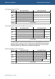
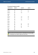
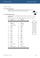
PC/104 interrupt register [PC104I1]
Byte lane Most Significant Byte Least Significant Byte
Bit 15 14 13 12 11 10 9 8 7 6 5 4 3 2 1 0
Field - - - - - - - -
IRQ12 IRQ11 IRQ10 IRQ7 IRQ6 IRQ5 IRQ4 IRQ3
Reset X X X X X X X X 0 0 0 0 0 0 0 0
R/W - - - - - - - - R/W
Address 0x14100000
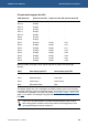
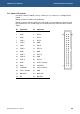
PC/104 interrupt register [PC104I2] (not available under Windows CE)
Byte lane Most Significant Byte Least Significant Byte
Bit 15 14 13 12 11 10 9 8 7 6 5 4 3 2 1 0
Field - - - - - - - - - - - - -
IRQ15 IRQ14 IRQ9
Reset X X X X X X X X 0 0 0 0 0 0 0 0
R/W - - - - - - - - R R/W
Address 0x14100004
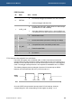
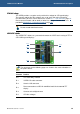
The ICR Register located at offset 0x100002 from CS5 (0x14000000) must be set-up
correctly for the OS running. The PC/104 interrupts are signalled and handled slightly
differently between embedded Linux / VxWorks and Windows CE. See the following
relevant subsections for specific PC/104 details for the target OS.
Interrupt configuration and reset register [ICR]
Byte lane Most Significant Byte Least Significant Byte
Bit 15 14 13 12 11 10 9 8 7 6 5 4 3 2 1 0
Field - - - - - - - - - - - -
CF_
RST
R_DIS
AUTO
_
CLR
RETRIG
Reset X X X X X X X X 0 0 0 0 0 0 0 0
R/W - - - - - - - - R R/W
Address 0x14100002