
Computer Hardware User Manual

VIPER Technical Manual Detailed hardware description
© 2007 Eurotech Ltd Issue E 37
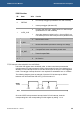
Typically the power up sequence is as follows (please check the datasheet for the
particular panel in use):
1 Enable display VCC.
2 Enable flat panel interface.
3 Enable backlight.
Power down is in reverse order.
LCD backlight enable
The PXA255 GPIO9 pin controls the LCD inverter supply voltage for the backlight.
When GPIO9 is set to logic ‘1’, the backlight supply BLKSAFE is supplied with 5V
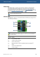
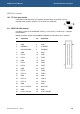
(turned on). The BLKEN signal on PL3 is the un-buffered GPIO9 signal. See the
section
348HPL3 – LCD connector, page 349H88, for PL3 pin assignment, connector and mating
connector details.
If you want to use a 12V backlight inverter, then the switched 5V supply on
BLKSAFE or the control signal BLKEN can be used to control an external 12V
supply to the inverter.
LCD logic supply enable
The PXA255 GPIO10 pin controls the supply voltage for the LCD logic. When GPIO10
is set to logic ‘1’, the LCD supply LCDSAFE is supplied with 3.3V (turned on). See the
section
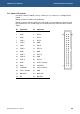
350HPL3 – LCD connector, page 351H88, for PL3 pin assignment, connector and mating
connector details.
The LCD supply may be changed to 5V by moving the jumper position of JP2
(see section
55HLCD Supply Voltage – LK8 on JP2, page 352H100 for details). If the
flat panel logic is powered from 5V, it must be compatible with 3.3V signalling.
Please check the LCD panel datasheet for details.
LCD backlight brightness control
The control of the backlight brightness is dependant upon the type of backlight inverter
used in the display. Some inverters have a ‘DIM’ function, which uses a logic level to
choose between two levels of intensity. If this is the case then GPIO16 (Alternative
Function 0) is used to set this. Other inverters have an input suitable for a pulse-width
modulated signal; in this case GPIO16 should be configured as PWM0 (Alternative
Function 2).