
Computer Hardware User Manual

VIPER Technical Manual Detailed hardware description
© 2007 Eurotech Ltd Issue E 58
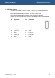
To write to OUT[0:7], write to the following PXA255 processor GPIO lines to drive the
outputs.
VIPER outputs PXA255 GPIO
OUT0 GPIO20
OUT1 GPIO21
OUT2 GPIO22
OUT3 GPIO23
OUT4 GPIO24
OUT5 GPIO25
OUT6 GPIO26
OUT7 GPIO27
The PXA255 GPIO lines must be configured using the registers built into the device to
ensure they function correctly. RedBoot configures GPIO20 – GPIO27 as outputs, and
sets OUT0 to logic ‘0’, and OUT1 – 7 as logic ‘1’. Eboot cannot set these up as outputs
as it only boots the Windows CE image. Once Windows CE is booted you can simply
write to a mapped address. For an example of how to do this under Windows CE
please see the Windows CE Technical Manual.
Please note:
• IN0-7 cannot be configured as outputs as they are hardwired as input-only
by a buffer.
• OUT0-7 cannot be configured as inputs as they are hardwired as
output-only by a buffer.
• OUT6-7 are not available if the VIPER is fitted with the TPM IC.
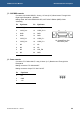
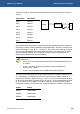
The GPIO lines are programmed using the GPCR0 and the GPSR0 to set the line to ‘0’
or ‘1’ respectively. The registers are 32-bit wide and bits 20-27 relate to GP20-27. To
set one of the GP20-27 signals to a logic ‘1’ write a ‘1’ to the corresponding GPSR0 bit.
To set one of the GP20-27 signals to a logic ‘0’ write a ‘1’ to the corresponding GPCR0
bit. To monitor the current state of a GP20-27 signal line read from GPLR0. A read-
modify-write operation to GPLR0 will not change the state of the GP20-27 signal lines.
Register Address
GPLR0 0x40E00000
GPSR0 0x40E00018
GPCR0 0x40E00024
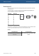
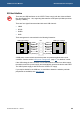
PXA255
Transceiver
PL9
GPIO[20:27]
OUT[0:7]
OUT0B