ZEUS PXA270 RISC based EPIC Single Board Computer Technical Manual
ZEUS Technical Manual Definitions Eurotech is the trading name for Eurotech Ltd. Disclaimer The information in this manual has been carefully checked and is believed to be accurate. Eurotech assumes no responsibility for any infringements of patents or other rights of third parties, which may result from its use. Eurotech assumes no responsibility for any inaccuracies that may be contained in this document. Eurotech makes no commitment to update or keep current the information contained in this manual.
ZEUS Technical Manual Contents Contents Product handling and environmental compliance ..............................................................................5 Introduction ........................................................................................................................................6 ZEUS ‘at a glance’ .................................................................................................................8 ZEUS features .............................................
ZEUS Technical Manual Contents Appendix B - Specification ...............................................................................................................98 Appendix C - Mechanical diagram .................................................................................................100 Appendix D - Reference information..............................................................................................102 Appendix E - Wireless modem datasheets ..................................
ZEUS Technical Manual Product handling and environmental compliance Product handling and environmental compliance Anti-static handling This board contains CMOS devices that could be damaged in the event of static electricity being discharged through them. At all times, please observe anti-static precautions when handling the board. This includes storing the board in appropriate anti-static packaging and wearing a wrist strap when handling the board.
ZEUS Technical Manual Introduction Introduction The ZEUS is an ultra-low power, high performance, single board computer based on the PXA270 processor. The PXA270 is an implementation of the Intel XScale micro architecture, combined with a comprehensive set of integrated peripherals including: • Flat panel graphics controller. • Interrupt controller. • Real time clock. • Various serial interfaces. The ZEUS board is based on the EPIC form factor. Included as standard are: • 2 Ethernet ports.
ZEUS Technical Manual Introduction Variant Details ZEUS-M64-F32-003-R6 Main features (all other features are included unless otherwise stated): ZEUS-M128-F32-004-I-R6* ZEUS-Mx-Fy-zzz-R6 ZEUS-Mx-Fy-zzz-I-R6* * • 5V only (No DC/DC PSU). • No CAN bus, LVDS or secondary Ethernet port. • 520MHz processor. Main features (all other features are included unless otherwise stated): • Industrial temperature range (-40°C to +85°C). • 5V only (No DC/DC PSU). • 416MHz processor.
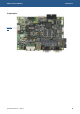
ZEUS Technical Manual Introduction ZEUS ‘at a glance’ 10-30V input option Audio GPIO SRAM Camera PXA270 DRAM Flat panel LCD Touchscreen 4-wire/5-wire Flat panel LCD – LVDS CAN bus Reset switch Flash JTAG Serial RS422/485 User jumpers 2x serial RS232/ 485/422 10-30V User Power input LEDs 2x Ethernet 2x USB host USB client Serial PC/104 Serial RS232 RS232 SD/SDIO/ MMC IEEE 802.15.
ZEUS Technical Manual Introduction 5V input option 5V power input © 2007 Eurotech Ltd Issue D 9
ZEUS Technical Manual Introduction ZEUS features Microprocessor • PXA270 312/416/520MHz processor (520MHz fitted as standard). Cache • System memory • 32K data cache, 32K instruction cache, 2K mini data cache. Fixed on-board memory: - 64/128/256 MB SDRAM (32-bit wide SDRAM data bus). Flash memory • Fixed on-board memory - 32/64MB Flash. • 256 KB of SRAM battery backed on board. • 18-bit flat panel interface for STN and TFT displays. • Optional LVDS interface.
ZEUS Technical Manual Introduction Expansion interfaces • CompactFlash CF+ socket to support Type I,II form factor CF+ cards. • SDIO socket to support MMC/SD/SDIO cards. • 16-bit PC/104 interface. Date/time support • Real time clock – battery backed on-board (external to PXA270). Audio and touchscreen • Wolfson WM9712L AC’97 compatible CODEC.! • Line in, line out, microphone in, stereo amp out. • Touchscreen support – 4/5-wire analogue resistive.
ZEUS Technical Manual Introduction Mechanical • EPIC form factor (115mm x 165mm). • Operating temperature: - Commercial: -20°C (-4°F) to +70°C (+158°F) for speed variants up to 520MHz. - Industrial: -40°C (-40°F) to +85°C (+185°F) for speed variants up to 416MHz. • RoHS Directive Compliant (2002/95/EC).
ZEUS Technical Manual Introduction ZEUS support products The following products support the ZEUS: • ZEUS Modem Board 1, a low profile module attached to the solder side of the ZEUS main board. It provides the following wireless connectivity options: - Quad band GSM/GPRS: Sony Ericsson GR64 or Dual band Siemens MC39i module. - iDEN: Motorola iO270 module (includes internal GPS receiver). - GPS: Fastrax iTRAX0312 channel GPS receiver module. See ZEUS Modem Board 1, page 118, for further details.
ZEUS Technical Manual About this manual About this manual This manual describes the operation and use of the ZEUS single board computer. It is designed to be a reference and user manual and includes information about all aspects of the board. Conventions Symbols The following symbols are used in this guide: Symbol Explanation Note - information that requires your attention. Tip - a handy hint that may provide a useful alternative or save time.
ZEUS Technical Manual About this manual Tables With tables such as that shown below, the white cells show information relevant to the subject being discussed. Grey cells are not relevant in the current context.
ZEUS Technical Manual Getting started Getting started A ZEUS Quickstart Manual is provided with each Development Kit to enable you to set up and start using the ZEUS board. Please read the relevant manual and follow the steps explaining how to set up the board. Once you have completed this task, and your ZEUS system is working, you can start adding further peripherals enabling development to begin. This section explains how to set up and use some of the features of the ZEUS.
ZEUS Technical Manual Getting started Using the Ethernet interface The boot loader configures the Davicom DM9000A 10/100BaseTX Ethernet controller. Connection is made via a dual RJ45 connector. See the sections Ethernet, page 52, and J6 – Ethernet connector, page 80, for further details. Using the PC/104 expansion bus PC/104 modules can be used with the ZEUS to add extra functionality to the system. This interface supports 8/16 bit ISA bus style peripherals.
ZEUS Technical Manual Detailed hardware description Detailed hardware description This section provides a detailed description of the functions provided by the ZEUS. This information may be required during development after you have started adding extra peripherals, or are starting to use some of the embedded features.
ZEUS Technical Manual Detailed hardware description ZEUS address map PXA270 chip select Physical address Bus width Description CS0# CS1# CS2# CS3# CS4# CS5# - 0x00000000 – 0x03FFFFFE 0x04000000 – 0x07FFFFFE 0x08000000 – 0x0BFFFFFE 0x0C000000 – 0x0FFFFFFF 0x10000000 – 0x11FFFFFE 0x12000000 – 0x13FFFFFE 0x14000000 – 0x17FFFFFE 0x18000000 – 0x1FFFFFFF 0x20000000 – 0x2FFFFFFE 0x30000000 – 0x300003FF 0x30000400 – 0x3BFFFFFF 0x3C000000 – 0x3C1FFFFF 0x3C200000 – 0x3FFFFFFF 0x40000000 – 0x43FFFFFF 0x44000000 –
ZEUS Technical Manual Detailed hardware description PXA270 processor The ZEUS board is based on a PXA270 processor. The PXA270 processor is an integrated system-on-a-chip microprocessor for high performance, low power portable handheld and handset devices. It incorporates the Intel XScale technology with on-thefly voltage and frequency scaling and sophisticated power management.
ZEUS Technical Manual Detailed hardware description The design supports 520MHz, 416MHz and 312MHz speed variants of the PXA270 processor. The standard variant of the ZEUS board is fitted with the 520MHz version of PXA270. The maximum speed available for extended temperature versions of the ZEUS is 416MHz. A 13MHz external crystal is used to run the PXA270 processor. All other clocks are generated internally in the processor.
ZEUS Technical Manual Detailed hardware description PXA270 GPIO pin assignments The table below summarizes the use of the 118 PXA270 GPIO pins, their direction, alternate function and active level. Key: AF Dir Active Alternate function. Pin direction. Function active level or edge. For details of pin states during sleep modes and reset see the Pin Usage table in the Intel PXA27x Processor Family Electrical, Mechanical and Thermal Specification.
ZEUS Technical Manual Detailed hardware description GPIO No AF Signal name Dir Active Function Wake-up source See section… Ethernet 0 Interrupt 3 Ethernet, page 52 14 0 ETH0_IRQ# Input 15 2 ETH_CS1# Output 16 2 PWM0 See Inverter Backlight Brightness On/Off Output data or variable if PWM sheet 17 0 ISA_IRQ Input 18 0 RESERVED 19 0 BKLEN Output 20 0 ISA_RST# Input 21 0 LVDS_EN Output High LVDS Transceiver Enable LVDS interface, page 47 22 0 USB_PWE2 Output High USB Port 2 P
ZEUS Technical Manual Detailed hardware description GPIO No AF Signal name Dir Active Function Wake-up source See section… 32 2 MMCLK Output NA SDIO Clock SDIO, page 39 33 2 SRAM_CS5# Output Low Chip Select 5 - SRAM Static RAM, page 34 34 1 GSM_FFRXD Input NA Modem Receive Data Wireless modem and GPS receiver, page 35 35 0 CF_CD# Input 36 1 GSM_FFDCD# Input NA Modem Data Carrier Detect 37 1 GSM_FFDSR# Input NA Modem Data Sender Ready 38 1 GSM_FFRI# Input NA Modem Ring
ZEUS Technical Manual Detailed hardware description GPIO No AF Signal name Dir Active Function 52 0 MMC_WP Input 53 0 MMC_CD Input 54 2 CB_PCE2# Output Low Card Bus High Byte Enable 55 2 CB_PREG# Output Low Card Bus Register Space Select 56 1 CB_WAIT# Input Low Card Bus WAIT# 57 1 CB_PIOIS16# Input Low Card Bus IOIS16# 58 2 LCD_D0 Output NA LCD Data Bit 0 59 2 LCD_D1 Output NA LCD Data Bit 1 60 2 LCD_D2 Output NA LCD Data Bit 2 61 2 LCD_D3 Output NA LCD Data
ZEUS Technical Manual Detailed hardware description GPIO No AF Signal name Dir Active Function Wake-up source See section… 78 2 ETH_CS2# Output NA Chip Select 2 - Ethernet 1 Ethernet, page 52 79 1 CB_PSKTSEL Output NA Card Bus Socket Select Expansion interfaces, page 38 80 2 CPLD_CS4# Output Low Chip Select 4 – UART/CPLD UART and CPLD address map, page 19 81 1 SPI_TXD3 Output NA SPI Transmit Data 82 1 SPI_RXD3 Input NA SPI Receive Data CAN bus, page 57 83 1 SPI_CS3# Output
ZEUS Technical Manual Detailed hardware description GPIO No AF Signal name Dir Active Function Wake-up source See section… Compact Flash Power Enable CompactFlash, page 40 NA Camera Interface Data 0 Quick Capture camera interface, page 59 Input NA Compact Flash Ready/Busy Status Flag CompactFlash, page 40 100 3 GSM_FFCTS# Input NA Modem Clear To Send Wireless modem and GPS receiver, page 35 101 0 LCD_EN 102 0 USER_LINK2 Input NA User Configurable 103 1 CIF_DD3 Input NA Camera In
ZEUS Technical Manual Detailed hardware description Interrupt assignments Internal interrupts For details on the PXA270 interrupt controller and internal peripheral interrupts please see the Intel PXA27x Processor Family Developer’s Manual on the Development Kit CD.
ZEUS Technical Manual Detailed hardware description On-Board GPIO expanders pin assignments Two GPIO expanders (MAX7313) are used to provide additional GPIOs for use with different on-board peripherals. The GPIO expanders are connected to the I2C bus of PXA270 and are accessible through I2C bus addresses 0x21 and 0x22. The following tables summarize the use of the 17 GPIO pins of MAX7313 on ZEUS board, and indicate their direction and active level.
ZEUS Technical Manual Detailed hardware description Expander 2 - I2C Address 0x22 Power-up state See section… GPIO Signal name Dir Active Function 0 CLK_SHDN# Output Low Clock Synthesizer Shutdown PU Clock generator power management, page 72 1 LVDS_FES# Output Low LVDS Falling Edge Strobe PU LVDS interface, page 47 2 CAN_SHDN Output High CAN Transceiver shutdown PU CAN bus, page 57 3 U1_RS232_SHDN# Output Low COM1 RS232 PU transceiver shutdown COM Ports power management, page
ZEUS Technical Manual Detailed hardware description Real time clock The ZEUS uses an external real time clock (RTC) (Intersil ISL1208) to store the date and time, and provide power management events. The RTC is connected to the I2C bus of the PXA270 processor and is accessible through I2C bus address 0x6F. The RTC is battery backed. The accuracy of the RTC is based on the operation of the 32.768 KHz watch crystal.
ZEUS Technical Manual Detailed hardware description Watchdog timer The ZEUS uses an external watchdog timer (MAX6369) which can be used to protect against erroneous software. This is a programmable watchdog timer that can be adjusted for timeout periods of 1ms, 10ms, 30ms, 100ms, 1s, 10s and 60s. The board is reset when timeout occurs. The MAX6369 watchdog timer can be programmed using the WD setup register provided within the CPLD. The register is memory mapped (accessible through CS5#).
ZEUS Technical Manual Detailed hardware description Memory The ZEUS has four types of memory fitted: • 32 or 64MB resident Flash disk containing: - Boot loader to boot operating system. - Operating system. - Application images. • 64, 128 or 256MB of SDRAM for system memory. • Static RAM, as follows: - 256KB of SRAM internal to PXA270. - 256KB of SRAM external to PXA270 (battery backed). • 128 bytes of configuration EEPROM on the I²C bus.
ZEUS Technical Manual Detailed hardware description Static RAM The PXA270 processor provides 256KB of internal memory-mapped SRAM. The SRAM is divided into four banks, each consisting of 64KB. The ZEUS also has an external 256KB SRAM device fitted, arranged as 256Kbit x 8bits. Access to the device is on 16-bit boundaries, whereby the least significant byte is the SRAM data and the 8-bits of the most significant byte are ‘don’t care’ bits.
ZEUS Technical Manual Detailed hardware description Wireless support The ZEUS can support various wireless modems, GPS functionality and an IEEE802.15.4 / ZigBee wireless sensor network interface. This is achieved using two optional add-on modules. GPS and cellular functionality are integrated on a single module (ZEUS Modem-n) while the IEEE802.15.4 / ZigBee port is provided by a separate module. Other cellular wireless modems such as EVDO, EDGE or satellite modems may be supported via this interface.
ZEUS Technical Manual Detailed hardware description ZEUS Modem-1 supports the following modules: • Sony Ericsson GR64, a quad-band (850/900/1800/1900) version of GR47/48. Functionally comparable to the Sony Ericsson GR47/GR48 devices, the GR64 offers a broad range of voice and data features. The integrated TCP/IP stack enables effective use of GPRS. For further details see Sony Ericsson GR64, page 104. • Siemens MC35i/39i, a dual-band GSM/GPRS module (EGSM 900/1800MHz).
ZEUS Technical Manual Detailed hardware description IEEE802.15.4 / ZigBee module (ZMx) IEEE802.15.4 / ZigBee is the wireless standards-based technology that addresses the unique needs of remote monitoring and control for sensor level network applications. ZigBee enables deployment of wireless networks with low cost, low power solutions sensor devices and offers the ability to run remote sensors for years on inexpensive primary batteries. For more information, see www.zigbee.org/en/about/.
ZEUS Technical Manual Detailed hardware description Expansion interfaces There are three expansion interfaces on the ZEUS: SDIO, PC/104 and CompactFlash. PC/104 and CompactFlash interfaces are connected to the PC card memory controller of the PXA270 with the use of some ‘glue logic’ implemented in a CPLD (Xilinx XC9536XL). There is a CPLD Firmware version/issue register that can be accessed at the address 0x12000000.
ZEUS Technical Manual Detailed hardware description SDIO The SD card socket J22 is interfaced directly to PXA270’s MMC/SD/SDIO controller. The MMC/SD/SDIO controller supports multimedia card, secure digital and secure digital I/O communications protocols. The MMC controller supports the MMC system, a low cost data storage and communications system. The MMC controller in the PXA270 processor is based on the standards outlined in the MultiMediaCard System Specification Version 3.2.
ZEUS Technical Manual Detailed hardware description CompactFlash A CompactFlash extension socket for full I/O mode operation is provided by slot 0 of the PXA270 PC card controller, and supports type I,II CF+ cards. It appears in PC card memory space socket 0. Address Region name 0x20000000 – 0x23FFFFFF Socket 0 I/O Space. 0x24000000 – 0x27FFFFFF Reserved. 0x28000000 – 0x2BFFFFFF Socket 0 Attribute Memory Space. 0x2C000000 – 0x2FFFFFFF Socket 0 Common Memory Space. This is a hot swappable 3.
ZEUS Technical Manual Detailed hardware description PC/104 interface The ZEUS PC/104 interface is emulated from the PXA270 PC card interface to support 8/16 bit ISA bus style signals. As the interface is an emulation, the ZEUS does not support some PC/104 features. Please refer to the section Unsupported PC/104 interface features on page 43 for specific details. Add-on boards can be stacked via the PC/104 interface to enhance the functionality of the ZEUS.
ZEUS Technical Manual Detailed hardware description PC/104 interrupts The PC/104 interrupts are combined together so that any interrupt generated on the PC/104 interface generates a single interrupt on the GPIO17 pin of the PXA270 processor. Reading the PC104_IRQ register located at the address 0x12800000 can identify the PC/104 interrupting source. The registers indicate the status of the interrupt lines at the time the register is read. The relevant interrupt has its corresponding bit set to ‘1’.
ZEUS Technical Manual Detailed hardware description Unsupported PC/104 interface features The ZEUS does not support the following PC/104 bus features: • PC/104 IRQ9, IRQ14 and IRQ15 are not available. • DMA is not supported. Therefore, AEN signal is set to a constant logical zero. • Bus mastering is not supported. Therefore, do not connect any other master addon board to the ZEUS PC/104 interface. • Shared interrupts are not supported.
ZEUS Technical Manual Detailed hardware description Flat panel display The PXA270 processor contains an integrated LCD display controller. It is capable of supporting both colour and monochrome single- and dual-scan display modules. It supports active (TFT) and passive (STN) LCD displays up to 800x600 pixels. The PXA270 can drive displays with a resolution up to 800x600, but as the PXA270 has a unified memory structure, the bandwidth to the application decreases significantly.
ZEUS Technical Manual Detailed hardware description Panel data bus bit 18-bit TFT 12-bit TFT 9-bit TFT FPD 7 G2 G0 - FPD 6 G1 - - FPD 5 G0 - - FPD 4 B5 B3 B2 FPD 3 B4 B2 B1 FPD 2 B3 B1 B0 FPD 1 B2 B0 - FPD 0 B1 - - GND B0 - - STN panel data bit mapping to the ZEUS Panel data bus bit Dual scan colour STN Single scan colour STN Dual scan mono STN FPD 15 DL7(G) - - FPD 14 DL6(R) - - FPD 13 DL5(B) - - FPD 12 DL4(G) - - FPD 11 DL3(R) - - FPD 10 D
ZEUS Technical Manual Detailed hardware description LCD logic and backlight power The display signals are +3.3V compatible. The ZEUS contains power control circuitry for the flat panel logic supply and backlight supply. The flat panel logic is supplied with a switched 3.3V (default) or 5V supply (for details see the section JP3 – LCD logic supply selection, page 94). The backlight is supplied with a switched 5V supply for the inverter.
ZEUS Technical Manual Detailed hardware description LCD backlight brightness control GPIO16 of the PXA270 processor is used for backlight brightness control (signal PWM0 on the J14 connector). The control of the backlight brightness is dependent upon the type of backlight inverter used with the display. Some inverters have a ‘DIM’ function, which uses a logic level to choose between two levels of intensity. If this is the case then GPIO16 (Alternative Function 0) is used to set this.
ZEUS Technical Manual Detailed hardware description The LVDS transmitter can be programmed for rising edge strobe or falling edge strobe operation through a signal LVDS_FES# (Expander 2 – GPIO1, I2C address 0x22). Details are shown in the following table: LVDS_FES# (EXP2_GPIO1) Selected LVDS function 0 Falling edge strobe 1 Rising edge strobe (default) Connector J24 should be used to supply the power and brightness control for the backlight inverter when the LVDS interface is used.
ZEUS Technical Manual Detailed hardware description Audio A Wolfson WM9712L AC’97 audio CODEC is used to support the audio features of the ZEUS. Audio inputs supported by the WM9712L are stereo line in and a mono microphone input. The WM9712L provides a stereo line out that is amplified by a National Semiconductor LM4880 250mW per channel power amplifier, suitable for driving an 8Ω load. The WM9712L AC’97 codec may be turned off if it is not required.
ZEUS Technical Manual Detailed hardware description Touchscreen controller The ZEUS supports 4-wire and 5-wire analogue resistive touchscreens using the controller available within the Wolfson WM9712L audio CODEC. The touchscreen controller supports the following functions: • X co-ordinate measurement. • Y co-ordinate measurement. • Pen down detection with programmable sensitivity. • Touch pressure measurement (4-wire touchscreen only).
ZEUS Technical Manual Detailed hardware description USB There are two USB host interfaces on the ZEUS. These comply with the Universal Serial Bus Specification Rev. 1.1, supporting data transfer at full-speed (12Mbit/s) and low-speed (1.5Mbit/s). There are four signal lines associated with each USB channel: VBUS, DATA+, DATA-, GND. The USB host ports are connected to a dual USB connector, type A (J8). A USB power control switch controls the power and protects against short-circuit conditions.
ZEUS Technical Manual Detailed hardware description Ethernet The ZEUS SBC provides two 10/100-BaseTX interfaces with MAC and complies with both the IEEE802.3u 10/100-BaseTX and the IEEE 802.3x full-duplex flow control specifications. Two single 10/100-BaseTX Ethernet controllers, Davicom DM9000A, are used to implement Ethernet interfaces on ZEUS. DM9000A device provides an embedded PHY and MAC and connects to 10/100-BaseTX magnetics. DM9000A also supports AUTOMDIX feature.
ZEUS Technical Manual Detailed hardware description Serial COM ports There are seven serial communications ports available on the ZEUS. Three are provided by the PXA270 and are used for the optional wireless modem, GPS and IEEE802.15.4 / ZigBee ports. There are four additional high-speed, 16550 compatible serial UARTs implemented by an EXAR ST16C554Q Quad UART device.
ZEUS Technical Manual Detailed hardware description COM3 – RS232/RS485/RS422 interface Supported on Channel C of the external Quad UART, COM3 port can be configured by software as RS232 or RS485/RS422. The port is buffered to RS232 (or RS485/RS422) levels with ±15kV ESD protection. RS232 interface supports full handshaking and modem control signals. The maximum baud rate on this channel is 921.6 Kbaud.
ZEUS Technical Manual Detailed hardware description COM4 – RS422/485 interface Supported on Channel D of the external Quad UART, and buffered to RS422/485 levels with ±15kV ESD protection, this channel provides support for RS422 or RS485 (software selectable) interfaces. The maximum baud rate on this channel is 921.6 Kbaud. COM4 port is connected to the connector J19.
ZEUS Technical Manual Detailed hardware description RS485 This is a half-duplex interface that provides combined TX and RX signals (TX+/RX+ and TX-/RX-). A ground connection is also required for this interface. The maximum cable length for this interface is the same as RS422 - 1200m (4000ft), but RS485 supports up to 32 transmitters and receivers on a single network. Only one transmitter should be switched on at a time. The ZEUS uses the RTS# signal to control transmission.
ZEUS Technical Manual Detailed hardware description CAN bus A Microchip MCP2515 CAN 2.0B protocol compatible controller and MCP2551 transceiver are used on the ZEUS to provide Controller Area Network (CAN) bus connectivity. CAN is a high-integrity serial data communications bus for real-time applications. It operates at data rates of up to 1 Mbit/s and has excellent error detection capabilities. A 16MHz clock is supplied to the CAN controller.
ZEUS Technical Manual Detailed hardware description I²C bus The PXA270 I²C interface is brought out to the COMs connector J19. See the section J19 – Serial ports – COM3/4, page 88, for connection details. I²C bus is also used with the Quick Capture interface. See the section Quick Capture camera interface, page 59.
ZEUS Technical Manual Detailed hardware description Quick Capture camera interface The Quick Capture camera interface is a component of Intel Quick Capture technology which provides a connection between the PXA270 processor and a camera image sensor. The Quick Capture interface is designed to work primarily with CMOS-type image sensors and supports up to 4 Megapixel resolution.
ZEUS Technical Manual Detailed hardware description External General purpose I/O A Maxim MAX7313 I²C I/O Expander provides sixteen general purpose input/output lines on the header J7. Each I/O port can be individually configured as either an opendrain current-sinking output rated at 50mA with10K pull-up to 5V, or a logic input with transition detection. The I/O Expander inputs are 5V tolerant.
ZEUS Technical Manual Detailed hardware description Temperature sensor There is a Philips LM75A temperature sensor on the ZEUS. The LM75A is a temperature-to-digital converter using an on-chip band-gap temperature sensor and sigma-delta A-to-D conversion technique. The device is also a thermal detector providing an over-temperature detection output (OVERTEMP signal on GPIO96 of PXA270). The accuracy of LM75A is ±2 °C (at -25 °C to 100 °C), and ±3 °C (at -55 °C to 125 °C).
ZEUS Technical Manual Detailed hardware description JTAG and debug access Debug access to the PXA270 processor is via the JTAG connector J5. A standard ARM 20-pin header is used for the JTAG interface. See J5 – JTAG connector, page 79, for details. Jumper JP7 needs to be inserted to enable the JTAG interface for PXA270 debug. See section JP7 - JTAG Enable, page 95 for details. The Macraigor Wiggler (see www.macraigor.com/wiggler.htm) and usb2Sprite (see www.macraigor.com/usb2sprite.
ZEUS Technical Manual Power and power management Power and power management Power supplies The ZEUS is designed to operate from a single +5V±5% (4.75V to +5.25V) input or the onboard 10V to 30V DC/DC PSU. DC input voltage (10-30V) DC input voltage (10-30V) is connected through a front panel locking DC jack J3 (see the section J3 – Power connector (10-30V), page 78). When operating from the 10 to 30V input, the 5V connector (J2) is NOT fitted.
ZEUS Technical Manual Power and power management On-board supplies There are seven on-board supply voltages derived from the +5V supply. They are listed in the following table: Supply rail Power domains Voltage Reset threshold VCC_BATT PXA270 Sleep-control subsystem, oscillators and real time clock 3.3V or 3.0V 2.25V VCC_CORE PXA270 core and other internal units 0.85V-1.55V 91% of nominal VCC_PLL PXA270 Phase-locked loops 1.3V 1.18V VCC_SRAM PXA270 Internal SRAM units 1.
ZEUS Technical Manual Power and power management Battery backup An on-board non-rechargeable coin cell battery (CR2032) provides a 3V battery backup supply for the ISL1208 RTC, external SRAM and the supply supervisor, when there is no +5V supply to the board. The ZEUS is normally shipped with battery disconnected. See JP2 – Battery disconnect, page 93, for details. The table below shows the typical and maximum current load on the backup battery: Device load on battery Typical (µA) Maximum (µA) SRAM 0.
ZEUS Technical Manual Power and power management Processor power management First available in the PXA270 processor, Wireless Intel SpeedStep Technology dynamically adjusts the power and performance of the processor based on CPU demand. This can result in a significant decrease in power consumption. In addition to the capabilities of Intel Dynamic Voltage Management, the Intel XScale micro architecture of the PXA27x family incorporates three new low power states.
ZEUS Technical Manual Power and power management Conditions System bus Frequency frequency Active power consumption typ. Idle power consumption typ. 520MHz 208MHz 747 mW 222 mW VCC_CORE = 1.45V 416MHz 208MHz 570 mW 186 mW VCC_CORE = 1.35V 312MHz 208MHz 390 mW 154 mW VCC_CORE = 1.25V 312MHz 104MHz 375 mW 109 mW VCC_CORE = 1.1V 208MHz 208MHz 279 mW 129 mW VCC_CORE = 1.15V 104MHz 104MHz 116 mW 64 mW VCC_CORE = 0.9V 13MHz CCCR[CPDIS]=1 44.2 mW - VCC_CORE = 0.
ZEUS Technical Manual Power and power management Peripheral devices power management The following table gives the estimated power consumption of on-board peripherals: Low power mode On-board peripheral Maximum power consumption Minimum consumption Operating mode Quad UART 66mW (20mA@3.3V) 10mW (3mA@3.3V) Idle Ethernet 2x DM9000A 607mW (2x92mA@3.3V) 46mW (2x7mA@3.3V) Power-down CAN MCP2515 50mW (10mA@5V) 0.025mW (5uA@5V) Sleep CAN transceiver 375mW (75mA@5V) 1.
ZEUS Technical Manual Power and power management The table below gives examples of power drawn by specific external peripheral devices: Device Part number Condition Power (mW) 64MB Sandisk CompactFlash SDCFJ-64 Sleep 1 Writing consistently 220 Socket WiFi 802.11b SDIO WL6200-480 Idle (listening) 50 Transmitting 925 64MB FlashDio USB memory stick FDU100A Inserted (no access) 375 Reading consistently 605 NEC 5.
ZEUS Technical Manual Power and power management CompactFlash power management The power supply to the CompactFlash interface is controlled via software, and supports hot swap card insertion and CompactFlash power down states. GPIO97 on the PXA270 (signal CF_PWEN) is used to control the power supply switch. Setting this line to logic ‘0’ switches off the power to the CompactFlash interface. The currentlimiting (1A) and thermal protection features of the power switch eliminate the need for the fuse.
ZEUS Technical Manual Power and power management Ethernet power management The Ethernet controllers (Davicom DM9000A) incorporate a number of features to maintain the lowest power consumption. The device can be put into a power-reduced mode by setting the PHY control register bit 16.4. In power-reduced mode, the device transmits the fast link pulses with minimum power consumption.
ZEUS Technical Manual Power and power management CAN bus power management The Microchip MCP2515 CAN bus controller has an internal sleep mode that is used to minimize the current consumption of the device. The SPI interface remains active for reading even when the MCP2515 is in sleep mode, allowing access to all registers. To enter sleep mode, the mode request bits are set in the CANCTRL register (REQOP<2:0>).
ZEUS Technical Manual Power and power management COM Ports power management RS232 transceivers can be placed in low power mode in case they are not used. This can reduce the power consumption of each RS232 transceiver down to 33 μW. GPIO pins 3 and 4 of Expander 2 (I2C address 0x22) are used to shut down COM1 and COM2. GPIO pin 1 of Expander 1 (I2C address 0x21) is used to shut down COM3.
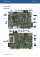
ZEUS Technical Manual Connectors, LEDs and jumpers Connectors, LEDs and jumpers The following diagram shows the location of the connectors, LEDs and jumpers on the ZEUS: J4 J7 JP2 JP3 J9 J24 J14 JP4 J1 J16 JP5&JP6 J2 J17 J5 J18 JP1 J19 © 2007 Eurotech Ltd J3 D3 J3 D3 Issue D J6 J6 J8 J8 J10 J11 J12&13 D10 J11 J15 J15 74
ZEUS Technical Manual Connectors, LEDs and jumpers J21 J22 J20 J23 The connectors on the following pages are shown in the same orientation as the pictures above, unless otherwise stated.
ZEUS Technical Manual Connectors, LEDs and jumpers Connectors There are 24 connectors on the ZEUS for accessing external devices: Connector Function Connector details in section… J1 Touchscreen controller J1 – Touchscreen connector, page 77 J2 Power (5V DC) J2 – Power connector (5V option), page 78 J3 Power (10-30V DC) J3 – Power connector (10-30V), page 78 (Please note that J3 is not fitted when J2 is fitted.
ZEUS Technical Manual Connectors, LEDs and jumpers Connector Function Connector details in section… J19 Serial ports (COM3/4) J19 – Serial ports – COM3/4, page 88 J20 CF+ interface J20 – CompactFlash , page 89 J21 IEEE802.15.4 / ZigBee J21 – IEEE802.15.
ZEUS Technical Manual Connectors, LEDs and jumpers J2 – Power connector (5V option) Connector: Neltron 5566S-08, 8-way, 4.2mm (0.165") pitch mini fit header Mating connector: Molex 39-01-2085, 8-way, 4.20mm (0.165") pitch mini-fit, receptacle housing Mating crimps: Molex 44476-1112 Pin Signal name Pin Signal name 1 GND 5 +5V 2 GND 6 +5V 3 GND 7 +5V 4 +12V 8 NC 5 1 8 4 +12V connection is defined, but is not required for the ZEUS under normal operation.
ZEUS Technical Manual Connectors, LEDs and jumpers J4 – Audio connector Connector: Neltron 2417SJ-12-PHD, 12-way, 2mm header Mating connector: JST PHDR-12VS Mating crimps: JST SPHD-002T-P0.5 Pin Signal name Pin Signal name 1 LEFT IN 2 LEFT OUT 3 GND 4 GND 5 RIGHT IN 6 RIGHT OUT 7 GND 8 AMP LEFT OUT 9 MIC VREF OUT 10 MIC IN 11 AMP RIGHT OUT 12 GND 1 11 2 12 J5 – JTAG connector Connector: Oupiin 2015-2x10-G-D W/ROHS, 20-way, 2.54mm (0.
ZEUS Technical Manual Connectors, LEDs and jumpers J6 – Ethernet connector Connector: Dual RJ45 shielded with LEDs, Xmultiple XRJM-S-02-8-8-1 Pin Signal name Pin Signal name 1A TX0+ 1B TX1+ 2A TX0- 2B TX1- 3A RX0+ 3B RX1+ 4A N.C. 4B N.C. 5A N.C. 5B N.C. 6A RX0- 6B RX1- 7A N.C. 7B N.C. 8A N.C. 8B N.C.
ZEUS Technical Manual Connectors, LEDs and jumpers J7 – GPIO connector Connector: Molex 87832-2020, 20-way, 2mm (0.079") header Mating connector: Molex 51110-2051, 2mm (0.
ZEUS Technical Manual Connectors, LEDs and jumpers J9 – Camera interface connector Connector: Neltron 2417RJ-20-PHD 'LEAD FREE', 20-way, 2mm (0.079") header Mating connector: JST PHDR-20VS Mating crimps: JST SPHD-002T-P0.
ZEUS Technical Manual Connectors, LEDs and jumpers J11 – Serial port – COM1 Connector: 9-pin D-type Plug male type Pin Signal name 1 DCD1 2 RX1 3 TX1 4 DTR1 5 GND 6 DSR1 7 RTS1 8 CTS1 9 RI1 © 2007 Eurotech Ltd Issue D 5 1 6 9 83
ZEUS Technical Manual Connectors, LEDs and jumpers J12 & J13 – PC/104 connectors Connector: • Samtec ESQ-132-12-G-D, 64-way, 2.54mm (0.1") PC/104 compatible connector (row A & B) • Samtec ESQ-120-14-G-D, 40-way, 2.54mm (0.
ZEUS Technical Manual Connectors, LEDs and jumpers J14 – LCD connector Connector: Oupiin 3214-40GRB, 40-way, 1.27mm (0.05") x 2.54mm (0.
ZEUS Technical Manual Connectors, LEDs and jumpers J15 – Serial port – COM2 Connector: 9-pin D-type plug, male type Pin Signal name 1 DCD2 2 RX2 3 TX2 4 DTR2 5 GND 6 DSR2 7 RTS2 8 CTS2 9 RI2 5 1 6 9 J16 – LVDS connector Connector: Hirose DF13-20DP-1.25V(55), 1.25mm pitch double row straight pin header Mating connector: Hirose DF13-20DS-1.
ZEUS Technical Manual Connectors, LEDs and jumpers J17 – CAN bus Connector: Neltron 2417SJ-5-F4, 5-way, 2mm (0.079") pitch wire-to-board header Mating connector: Molex 87369-0500 2mm (0.079") pitch crimp housing Mating crimps: Molex 50212 Pin Signal name 1 VCC_CAN (+5V) 2 CANH 3 CAN_SCRN 4 CANL 5 GND 1 5 J18 – Serial port (RS485/422) – COM3 Connector: Neltron 2417SJ-5-F4, 5-way, 2mm (0.079") pitch wire-to-board header Mating connector: Molex 87369-0500 2mm (0.
ZEUS Technical Manual Connectors, LEDs and jumpers J19 – Serial ports – COM3/4 Connector: Oupiin 3012-20GRB W/ROHS, 20-way, 2.54mm (0.1") dual row IDC boxed header Mating connector: FCC 71600-020LF Pin Signal name Pin Signal name 1 I2C_SCL 2 I2C_SDA 3 GND (I²C ) 4 3.
ZEUS Technical Manual Connectors, LEDs and jumpers J20 – CompactFlash connector Connector: 3M N7E50-M516RB-50, 50-way CompactFlash type II connector Pin Signal name Pin Signal name 1 GND 2 D3 3 D4 4 D5 5 D6 6 D7 7 CE1# 8 A10 9 OE# 10 A9 11 A8 12 A7 13 +3.
ZEUS Technical Manual Connectors, LEDs and jumpers J21 – IEEE802.15.4 / ZigBee connector Connector: Harwin M50-4321005, 20-way, 1.27mm dual row socket Mating connector: M50-4921005, 20-way, 1.27mm dual row header Pin Signal name Pin Signal name 1 +3V3 2 +3V3 3 GND 4 GND 5 NC 6 RESET# 7 ZB_BTRXD 8 ZB_BTTXD 9 ZB_BTCTS# 10 ZB_BTRTS# 11 NC 12 NC 13 NC 14 NC 15 NC 16 NC 17 NC 18 NC 19 NC 20 NC 2 20 1 19 J22 – SDIO socket Connector: Molex 67913-0002, 2.50mm (0.
ZEUS Technical Manual Connectors, LEDs and jumpers J23 – Wireless modem/GPS module interface Connector: Hirose DF17(4.0)-40DP-0.5V(57), 40-way, 0.5mm pitch header Mating connector: Hirose DF17(3.0)-40DS-0.5V(51), 40-way, 0.
ZEUS Technical Manual Connectors, LEDs and jumpers J24 – Backlight power (for flat panel displays) Connector: Molex 53047-0710, 7-way 1.25mm (0.049") pitch header with friction lock Mating connector: Molex 51021-0700, 7-way 1.25mm (0.
ZEUS Technical Manual Connectors, LEDs and jumpers Jumpers There are six user selectable jumpers on the ZEUS. Their use is explained below. JP1 – User jumpers Connector: 8-way, 2.54mm (0.
ZEUS Technical Manual Connectors, LEDs and jumpers JP3 – LCD logic supply selection Connector: 3-way, 2.54mm (0.1") single row through-hole header Pin Signal name 1 +5V 2 LCD Logic Supply 3 +3V3 3 1 This jumper selects the supply voltage for the LCD logic supply. JP3 Description 3 1 Supply LCD Logic with 5V 3 1 Supply LCD Logic with 3.3V (Default) If the LCD requires a 5V supply, please refer to the LCD datasheet to ensure that the display is compatible with 3.3V logic.
ZEUS Technical Manual Connectors, LEDs and jumpers JP5 & JP6 – CAN bus termination Connector: 2-way, 2.54mm (0.1") through-hole header JP5 JP6 Pin Signal name Pin Signal name JP5 1 CANH 1 Centre tap 2 2 Centre Tap 2 CANL JP5 & JP6 1 JP6 1 2 Description 62Ω Termination connected 62Ω Termination disconnected (default) Only insert jumpers JP5 and JP6 if the ZEUS is at the end of the network. JP7 - JTAG Enable Connector: 2-way, 2.54mm (0.
ZEUS Technical Manual Connectors, LEDs and jumpers Status LEDs Flash LED There is a single status LED (D10) on the ZEUS, which indicates access to the Flash memory. User LEDs There are three user LEDs on the ZEUS front panel (D3).
ZEUS Technical Manual Appendix A - Contacting Eurotech Appendix A - Contacting Eurotech Eurotech sales Eurotech’s sales team is always available to assist you in choosing the board that best meets your requirements. Eurotech Ltd 3 Clifton Court Cambridge CB1 7BN UK Tel: Fax: Email: +44 (0)1223 403410 +44 (0)1223 410457 sales@eurotech-ltd.co.uk Comprehensive information about our products is also available at our web site: www.eurotech-ltd.co.uk.
ZEUS Technical Manual Appendix B - Specification Appendix B - Specification Microprocessor • PXA270 312/416/520MHz processor (520MHz as standard option). Cache • System memory • 32K data cache, 32K instruction cache, 2K mini data cache. Fixed on-board memory: 64/128MB/256MB SDRAM (32-bit wide SDRAM data bus). Flash memory • Fixed on-board memory: 32/64MB Flash. • • 256KB of SRAM - battery backed on board. 256KB of SRAM internal to PXA270.
ZEUS Technical Manual Appendix B - Specification Video • • 18-bit flat panel interface for STN and TFT displays. Optional LVDS interface. Audio and touchscreen • AC’97 compatible CODEC.! • Touchscreen support – 4/5-wire analogue resistive. Quick Capture camera interface • Intel Quick Capture technology. I2C bus • Multi-master serial bus. Configuration EPROM • I2C EPROM for storing configuration data. CAN bus • Watchdog timer • Optional CAN 2.0B protocol controller and opto-isolated transceiver.
ZEUS Technical Manual Appendix C - Mechanical diagram Appendix C - Mechanical diagram All dimensions are shown in mm.
ZEUS Technical Manual Appendix C - Mechanical diagram When mounting the ZEUS use only M3 (metric) or 4-40 (Imperial) screws. The mounting pad is 6.35mm (0.25") and the hole is 3.175mm (0.125"), so ensure any washers fitted are smaller than the pad. Using oversized screws and washers, or tooth locking washers, can cause short circuits and over-voltage conditions. We recommend that you use a Loctite screw thread lock or a similar product over tooth locking washers.
ZEUS Technical Manual Appendix D - Reference information Appendix D - Reference information Product information Product notices, updated drivers, support material, 24hr-online ordering: www.eurotech-ltd.co.uk EPIC information Embedded Platform for Industrial Computing: www.pc104.org/technology/PDF/EPIC_Spec_2.0.pdf PC/104 Consortium PC/104 Specifications - vendor information and available add on products: www.pc104.
ZEUS Technical Manual Appendix D - Reference information Intel PXA270 processor documentation: www.intel.com Marvell PXA270 processor documentation: www.marvell.com Exar Corporation Exar XR16C554DCQ Quad UART documentation: www.exar.com Wolfson Microelectronics Wolfson WM9712L AC’97Codec documentation: www.wolfson.co.uk Spansion S29GL-N MirrorBitTM Flash Family documentation: www.spansion.com Intersil RTC ISL1208 documentation: www.intersil.
ZEUS Technical Manual Appendix E - Wireless modem datasheets Appendix E - Wireless modem datasheets Sony Ericsson GR64 © 2007 Eurotech Ltd Issue D 104
ZEUS Technical Manual © 2007 Eurotech Ltd Issue D Appendix E - Wireless modem datasheets 105
ZEUS Technical Manual Appendix E - Wireless modem datasheets Siemens MC39i © 2007 Eurotech Ltd Issue D 106
ZEUS Technical Manual © 2007 Eurotech Ltd Issue D Appendix E - Wireless modem datasheets 107
ZEUS Technical Manual Appendix E - Wireless modem datasheets Fastrax iTrax03/08 © 2007 Eurotech Ltd Issue D 108
ZEUS Technical Manual © 2007 Eurotech Ltd Issue D Appendix E - Wireless modem datasheets 109
ZEUS Technical Manual Appendix E - Wireless modem datasheets Motorola iO270 © 2007 Eurotech Ltd Issue D 110
ZEUS Technical Manual © 2007 Eurotech Ltd Issue D Appendix E - Wireless modem datasheets 111
ZEUS Technical Manual Appendix E - Wireless modem datasheets Telit GE863-GPS © 2007 Eurotech Ltd Issue D 112
ZEUS Technical Manual © 2007 Eurotech Ltd Issue D Appendix E - Wireless modem datasheets 113
ZEUS Technical Manual Appendix E - Wireless modem datasheets Sierra Wireless MC8775 © 2007 Eurotech Ltd Issue D 114
ZEUS Technical Manual © 2007 Eurotech Ltd Issue D Appendix E - Wireless modem datasheets 115
ZEUS Technical Manual Appendix E - Wireless modem datasheets Sierra Wireless MC5720 © 2007 Eurotech Ltd Issue D 116
ZEUS Technical Manual © 2007 Eurotech Ltd Issue D Appendix E - Wireless modem datasheets 117
ZEUS Technical Manual Appendix F - ZEUS Modem details Appendix F - ZEUS Modem details ZEUS Modem-1 The following photos show the ZEUS Modem-1 with Fastrax GPS receiver and three possible options for wireless modem. J9 – iO270 audio JP1 SIM select J4 SIM card J3 iO270 J1 SONY GR64 ZEUS host interface GPS module J2 Siemens MC39i ZEUS Modem-2 The following photos show the ZEUS Modem-2 with Telit option for wireless modem.
ZEUS Technical Manual Appendix F - ZEUS Modem details ZEUS Modem-3 The following photos show the ZEUS Modem-3 with Fastrax GPS receiver and several possible options for Sierra Wireless embedded modules. J2 – Sierra wireless USB data (see below) J4 – SIM card J1 – Sierra Wireless module ZEUS host interface GPS module J2 –Sierra wireless USB data connector Connector: NELTRON 2417RJ-3-F4, 3-way 2mm header Mating connector: JST PHR-3, 3-way 2mm housing, female Mating crimps: JST SPH-002T-P0.
ZEUS Technical Manual Appendix F - ZEUS Modem details ZEUS Modem connector details ZEUS host interface Module connector: Hirose DF17(3.0)-40DS-0.5V(51), 40-way, 0.5mm pitch socket Host connector: Hirose DF17(4.0)-40DP-0.5V(57), 40-way, 0.
ZEUS Technical Manual Appendix F - ZEUS Modem details The following table shows the functions of control/status pins on the host interface: EXP1_GPIO Signal name Dir Active Function 7 PTT Output High Push To Talk.
ZEUS Technical Manual Appendix G - ZEUS-FPIF details Appendix G - ZEUS-FPIF details The ZEUS-FPIF allows easy connection between the ZEUS and a variety of TFT or STN LCD flat panel displays. J5 J2 JP1 J1 J3 J4 The connectors on the following pages are shown in the same orientation as the picture above. Connector Function JP1 TFT clock delay selection J1 ZEUS LCD cable connector J2 Generic LCD connector J3 Direct connection to a NEC NL3224BC35-20 5.
ZEUS Technical Manual Appendix G - ZEUS-FPIF details J1 – ZEUS LCD cable connector Connector: Oupiin 3215-40GSB/SN, 40-way, 1.27mm (0.05") x 2.54mm (0.
ZEUS Technical Manual Appendix G - ZEUS-FPIF details J2 – Generic LCD connector Connector: Taicom TI34BHS, 34-way, 2.54mm (0.1") x 2.54mm (0.1") straight-boxed header Mating connector: Fujitsu FCN-723-B034/2 Mating connector crimps: Fujitsu FCN-723J-AU/Q.
ZEUS Technical Manual Appendix G - ZEUS-FPIF details J3 – Direct connection to a NEC NL3224BC35-20 5.5inch 320x240 TFT display Connector: Oupiin 2345-33TD2/SN Mating cable: Eunsung 0.5x33x190xAx0.035x0.
ZEUS Technical Manual Appendix G - ZEUS-FPIF details J4 – Backlight inverter connector Connector: FCI 76384-407LF Mating connector: FCI 65240-007LF Mating connector crimps: FCI 76357-401LF Pin Signal name 1 BKLSAFE 2 BKLSAFE 3 GND 4 GND 5 BKLEN 6 BRT_CTRL 7 GND J5 – STN Bias connector Connector: FCI 76384-404LF Mating connector: FCI 65240-004LF Mating connector crimps: FCI 76357-401LF Pin Signal name 1 POSBIAS 2 GND 3 GND 4 NEGBIAS © 2007 Eurotech Ltd Issue D 126
ZEUS Technical Manual Appendix H - ZEUS-FPIF-CRT details Appendix H - ZEUS-FPIF-CRT details The ZEUS-FPIF-CRT allows the ZEUS to drive a CRT Monitor or an analogue LCD flat panel. Sync on green and composite sync monitors are not supported. J1 J2 The connectors on the following pages are shown in the same orientation as the picture above, unless otherwise stated.
ZEUS Technical Manual Appendix H - ZEUS-FPIF-CRT details J1 – ZEUS LCD cable connector Connector: Oupiin 3215-40CSB/SN, 40-way, 1.27mm (0.05") x 2.54mm (0.
ZEUS Technical Manual Appendix H - ZEUS-FPIF-CRT details J2 – CRT connector Connector: Oupiin 7916-15FA/SN, 15-way, female, high density, right-angled D-Sub.
ZEUS Technical Manual Appendix H - Acronyms and abbreviations Appendix H - Acronyms and abbreviations Amp BTUART CCCR CODEC COM CPLD CPU CMOS DMA DUART EEPROM EMC EPIC EPROM FFUART FIFO Flash FPIF GPIO I²C IEEE IO ISA JTAG LED LCD LSB LVDS MOSFET NA NC NU OS PC/104 PCB PoE PROM PWM RAM RTC RX SBC © 2007 Eurotech Ltd Issue D Amplifier Bluetooth Universal Asynchronous Receiver / Transmitter Core Clock Configuration Register Coder/Decoder Communication Port Complex Programmable Logic Device Central Proces
ZEUS Technical Manual SDIO SDRAM SRAM STN STUART SVGA TFT TX UART USB VAC VDC VGA WDT ZEUS-ICE © 2007 Eurotech Ltd Issue D Appendix H - Acronyms and abbreviations Secure Digital Input/Output Synchronous Dynamic Random Access Memory Static Random Access Memory Super Twisted Nematic, technology of passive matrix liquid crystal Standard Universal Asynchronous Receiver / Transmitter Super Video Graphics Adapter, display resolution 800 x 640 pixels Thin Film Transistor, a type of LCD flat-panel display scre
ZEUS Technical Manual Appendix I - RoHS-6 Compliance - Materials Declaration Form Appendix I - RoHS-6 Compliance - Materials Declaration Form Confirmation of Environmental Compatibility for Supplied Products Substance Maximum concentration Lead 0.1% by weight in homogeneous materials Mercury 0.1% by weight in homogeneous materials Hexavalent chromium 0.1% by weight in homogeneous materials Polybrominated biphenyls (PBBs) 0.
ZEUS Technical Manual Index Index A abbreviations · 131 acronyms · 131 active display signal · 45 address map · 19 anti-static · 5 Arcom, contacting · 97 assignments, GPIO pins · 22, 29 audio · 16, 49 connector · 79 power management · 71 COM1 · 53, 83 COM2 · 53, 86 COM3 · 54, 88 COM4 · 55, 88 CompactFlash · 16, 34, 40 connector · 89 power management · 70 configuration PROM power management · 73 connectors · 74, 76 contact details · 97 contacting Arcom · 97 B D backlight brightness · 47 inverter conne
ZEUS Technical Manual H hardware description · 18 I I/O expander, power management · 73 I²C bus · 58 interface · 52 internal interrupt · 28 interrupt · 28 external · 28 internal · 28 J J1 · 77 J10 · 82 J11 · 83 J12 · 84 J13 · 84 J14 · 85 J15 · 86 J16 · 86 J17 · 87 J18 · 87 J19 · 88 J2 · 78 J20 · 89 J21 · 90 J22 · 90 J23 · 91 J24 · 92 J3 · 78 J4 · 79 J5 · 79 J6 · 80 J7 · 81 J8 · 81 J9 · 82 JP1 · 93 JP2 · 93, 95 JP3 · 94 JP4 · 94 JP5 · 95 JP6 · 95 JTAG · 62 connector · 79 jumper diagrams · 14 jumpers · 74,
ZEUS Technical Manual Index S U sales team · 97 SDIO · 39 socket · 90 SDRAM · 33 serial ports · 16, 53, 57, 83, 86, 87, 88 silicon disk · 33 sleep mode · 67 source code · 97 specification · 98 static · 5 static RAM · 34 STN · 13, 45, 123, 128 bias connector · 127 bias voltage · 47 support products · 13 support, technical · 97 symbols · 14 USB client header · 82 connector · 81 interface · 51 ports · 16 power · 70 power management · 70 user jumpers · 93 user LEDs · 96 T tables · 15 technical support · 9
ZEUS Technical Manual Index S U sales team · 97 SDIO · 39 socket · 90 SDRAM · 33 serial ports · 16, 53, 57, 83, 86, 87, 88 silicon disk · 33 sleep mode · 67 source code · 97 specification · 98 static · 5 static RAM · 34 STN · 13, 45, 123, 128 bias connector · 127 bias voltage · 47 support products · 13 support, technical · 97 symbols · 14 USB client header · 82 connector · 81 interface · 51 ports · 16 power · 70 power management · 70 user jumpers · 93 user LEDs · 96 T tables · 15 technical support · 9