
User`s manual


Am186
TM
CC Microcontroller ISDN TA Reference Design Manual
2-16
ISDN TA Pin Usage
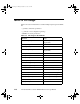
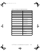
Table 2-3 shows the Am186CC microcontroller multiplexed pin usage for the ISDN
TA.
• [] indicates an alternate pin function.
• {} indicates a reset configuration (pinstrap).
• boldface denotes the pin function.
Table 2-3. Pin Usage for the ISDN TA
Pin Name Usage
TMROUT1 [PIO1] DCE serial port flow control for
Plug and Play
ARDY [PIO8] USB active LED
RTRA# [PIO18] ISDN B1-Channel active LED
TMROUT0 [PIO28] DCE serial port flow control for
Plug and Play
PCS7# [PIO31] Flash memory RY/BY
PCS6# [PIO32] ISDN D-Channel active LED
SRDY [PIO35] Flash memory A18
RTRB# [PIO39] ISDN B2-Channel active LED
RXDC [RXDC] [PIO42] USB detect
TXDC [TXDC] [PIO43] USB VCC enable
INT0 TIP - Ethernet IRQ
INT1 ISDN S/T transceiver interrupt
INT2 ISDN U transceiver interrupt
INT7 [PIO7] TIP - serial port 1 interrupt
INT8 [PWD] [PIO6] TIP - serial port 0 interrupt
UCS# [ONCE#] Flash memory CE#
LCS# [RAS0#] DRAM RAS#
about.book Page 16 Friday, December 18, 1998 9:41 AM