
User's Manual
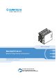


Table Of Contents
- Intended audience of this document
- How to get technical support
- Trademarks
- Revision history
- How to get started
- Contents
- 1 Safety-related information
- 2 Consignes de sécurité
- 3 Technical terms and graphical symbols
- 4 Termes techniques et symboles graphiques
- 5 Product Overview
- 6 Certifications
- 7 Main CPU Module interfaces
- 7.1 Main CPU Module connectors (vers: -11)
- 7.2 Main CPU Module connectors (vers: -21 and -31)
- 7.3 Main CPU Modules Interfaces
- 7.3.1 USB0 and USB1: USB 3.0 connectors specifications
- 7.3.2 DP: Mini DisplayPort specifications
- 7.3.3 ETH0, ETH1, ETH2: Gb Ethernet connectors specifications
- 7.3.4 PWR IN: Power IN connector specifications
- 7.3.5 Navigation system specifications
- 7.3.6 LTE cellular modem specifications
- 7.3.7 Wi-Fi and BT specifications (vers: -21 and -31 only)
- 7.3.8 MVB ESD+ (RX only or RX/TX) interface specifications (vers: -11 only)
- 7.3.9 Earth connection terminal specifications
- 7.4 Main CPU Module LED indicators
- 7.5 Main CPU Module Service Panel and Service Interfaces
- 8 BoltAIR 20-31 interfaces
- 9 BoltIO 20-31 interfaces
- 10 BoltSER 20-31 interfaces
- 11 Product installation and power supply
- 11.1 Introduction
- 11.2 How to install the product on a DIN Rail
- 11.3 How to remove the product from a DIN Rail
- 11.4 Mechanical specifications
- 11.5 How to supply power to the system
- 11.5.1 Power supply specifications
- 11.5.2 The Ignition Key (Key Signal)
- 11.5.3 Main CPU Module and Expansion Modules electrical interconnections
- 11.5.4 Power supply safety instructions
- 11.5.5 How to supply power and turn ON the product
- 11.5.6 How to turn OFF the system
- 11.5.7 How to trigger a hardware reset of the system
- 12 Eurotech Everyware IoT
- 13 Product maintenance
- Notes

BoltGATE 20-31 User's manual EN How to get started
© 2022 Eurotech SpA - Via Fratelli Solari 3/A - 33020 AMARO (UD) - Italy
Code: BTGATE-20-31_MAN_EN_1-6
Revision: 1-6 2022.07.28
3 / 98
HOW TO GET STARTED
To get started with the BoltGATE 20-31 complete this procedure::
1. Read carefully and understand the instructions and warnings contained in this User's
manual.
To lower the risk of personal injury, electric shock, fire, or damage to equipment, observe the
instructions and warnings contained in this manual.
For more information, refer to: "Safety-related information" on page9.
If you have questions about these instructions, refer to: https://www.eurotech.com/en/support.
2. Know the BoltGATE 20-31 and its interfaces.
For more information, refer to:
l
"Product Overview" on page21
l
"Technical specifications" on page24
l
"Main CPU Module interfaces" on page41
3. Install the BoltGATE 20-31.
For more information, refer to:
l
"Mechanical specifications" on page84
l
"Product installation and power supply" on page81
4. Supply power to the BoltGATE 20-31 respecting all safety instructions.
For more information, refer to:"How to supply power to the system" on page86
5. Start developing your IoT applications.
The BoltGATE 20-31 supports the Eurotech Everyware Software Framework (ESF). ESF is a
smart application container that enables remote management of IoT gateways and provides a
wide range of APIs allowing you to write and deploy your own IoT application.
For more information, refer to:
l
"Eurotech Everyware IoT" on page91
l
http://esf.eurotech.com/docs.