
Operating instructions

installation
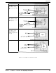
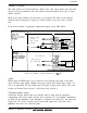
Resistance thermometer (RTD) Ptl 00, three-wire device
Connect the single wire of the sensor to terminal 19 and the double wire to terminals 18 20.
The length and gauge of all three wires must be equal. The cable resistance is compensated for
by the three-wire device. Sensor break display is shown only if two wires break
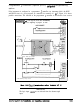
Sensor
External Connections
Terminals
no connection
Figure 2.3.5 Sensor input, Terminals 18, 19 20
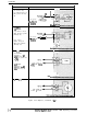
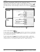
Linear input (Option
For input signals in the range to connection is made directly to the instrument.
As a precaution against interference, a shielded, twisted pair should be used. The shield should
only be grounded at the sensor end.
For input signals greater than
and process signals (per unit signals), a suitable input
adapter is available. This adapter is delivered with the instrument if ordered. Make sure that it
is installed directly on to the instrument terminals. Again, use a shielded, twisted pair.
2-8
Installation and Operating Instructions