Instruction Manual αlpha CON 2000 Conductivity/ Total Dissolved Solids Controller / Transmitter Technology Made Easy ...
Preface This manual serves to explain the use of the αlpha CON 2000 Series. The manual functions in two ways, firstly as a step by step guide to help the user operate the instrument, and secondly as a handy reference guide. This instruction manual is written to cover as many anticipated applications of the αlpha CON 2000 as possible. If you have any doubts concerning the use of the instrument, please do not hesitate to contact the nearest Eutech Instruments Authorised Distributor.
Safety Information This Eutech Instruments Controller/ Transmitter shall be installed and operated only in the manner specified in the Instruction manual. Only skilled, trained or authorised person should carry out installation, setup and operation of the instrument. Before powering up the unit, make sure that power source it is connected to, is as specified in the top label. Failure to do so may result in a permanent damage to the unit. The unit has live and exposed parts inside.
TABLE OF CONTENTS 1 INTRODUCTION ....................................................................................................................................... 1 1.1 1.2 1.3 1.4 2 AT THE VERY BEGINNING ...................................................................................................................... 1 INTENDED USE ...................................................................................................................................... 1 SAFETY INTSRUCTIONS .......
10.2 10.3 10.4 10.5 11 PACKAGING / SCOPE OF DELIVERY ...................................................................................................... 39 RETURN OF GOODS.............................................................................................................................. 39 GUIDELINES FOR RETURNING UNIT FOR REPAIR .................................................................................. 39 MAINTENANCE AND CLEANING .......................................................
αlpha CON 2000 Instruction Manual 1 INTRODUCTION 1.1 At the very beginning We thank you for having purchased the Eutech Instruments αlpha CON 2000. The construction of the αlpha CON 2000 employs leading edge technology and complies with safety regulations currently in force. Notwithstanding this, improper use could lead to hazards for the user or a third-party, and/or adverse effects on the plant or other equipment.
αlpha CON 2000 Instruction Manual 1.3 Safety intsructions The αlpha CON 2000 should be installed and operated only by personnel familiar with the transmitter and who are qualified for such work. A defective transmitter must neither be installed nor put into service. The αlpha CON 2000 must only be operated under the specified operating conditions (see section 8). The αlpha CON 2000 must not be repaired by the customer.
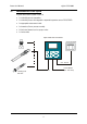
αlpha CON 2000 Instruction Manual 2 PRODUCT DESCRIPTION 2.1 Description of unit The Eutech Instruments αlpha CON 2000 is used for measuring conductivity and temperature values. The conductivity values can be measured using limit or P/PI control. The transmitter is available in two versions, one for panel mounting and one for wall mounting in a enclosure.
αlpha CON 2000 Instruction Manual 2.2 Measurement and control system A typical measurement system consists of: • A conductivity process transmitter • A conductivity sensor with integrated or separate temperature sensor Pt100/Pt1000.
αlpha CON 2000 Instruction Manual 2.
αlpha CON 2000 Instruction Manual 2.3.1 Display Overview The LC display shows two alpha-numerical fields for parameters and measured values as well as various mode and status indicators. SETUP MEAS Mode indicators: CAL MEAS: measurement mode mS µS HOLD SETUP: Set-up mode CAL: Calibration mode ERR Status indicator: °C °F 4 HOLD: Unit in “HOLD” mode ATC: Visible in ATC (Automatic Temperature Compensation) mode. Not visible in the Manual Temperature Compensation mode.
αlpha CON 2000 Instruction Manual 2.3.3 LED indicators Relay indicators If REL key is pressed the LED (A, B or W) indicates to which Relay (A, B or Wash) the displayed limit values refer. Relay mode indicators Auto LED lights if relay operation is set to automatic mode. Manu LED lights if relay operation is set to manual mode. Relay status indicators This LED lights if limit value is exceeded or the ATC probe fails.
αlpha CON 2000 Instruction Manual 2.3.5 Menu overview MEAS µS °C 4 CAL 1 ENTER ENT ENTER ENT 1 CCD “000” = Check calibration parameters (View only mode) CCD “11” = Calibration mode 2 SCD “000” = Check setup parameters (View only mode) SCD “22” = Setup mode 2 ENTER ENT SETUP HOLD ENT 4 SETUP HOLD ENT Temperature settings see section 6.
αlpha CON 2000 Instruction Manual 3 ASSEMBLY AND INSTALLATION 3.1 Mounting the unit Wall mounting version 111.50 [4.39] 144 [5.67] approx. 14 [.55] 144 [5.67] 27.5 [1.08] 39 [1.54] 78 [3.07] For Pg13.5 cable glands 24 [.94] Pg13.5 (3 pcs.) 57.8[2.28] Holes for post mounting (4X) 21.5 [.85] Holes for wall mounting (2X) 90 [3.54] 66.5 [2.62] 80 [3.15] 6 [.24] Unit: MM [INCH] 90 [3.
αlpha CON 2000 Instruction Manual Panel mounting version Flat gasket 1mm [.
αlpha CON 2000 Instruction Manual 3.2 Connection Diagram Caution: Ensure electrical mains are disconnected before proceeding. Connections for wall mounting version R ELA 4 29 + 28 - 31 + 30 20 19 22 14 13 - Curre nt Curre nt GND+1 2V OP 2 OP1 HOLD R ELB 5 24 25 6 26 WASH R ELAY 7 15 16 8 17 9 18 A LAR M R ELAY 12 11 3 2 PT10 0/ PT10 00 N 10 1 L RELA 4 29 + 28 - 31 + 30 20 19 14 13 - Current Current GND+12V OP 2 OP1 1. 2. 3. 4. 5. 6. 7. 8. 9. 10. 11. 12. 13. 14.
αlpha CON 2000 Instruction Manual NOTE: a) Switch or circuit breaker shall included in the building installation. b) It shall be in close proximity to the equipment and within easy reach of the operator. c) It shall be marked as the disconnecting device for the equipment.
αlpha CON 2000 Instruction Manual Connections for panel mounting version 1. 2. 3. 4. 5. 6. 7. 8. 9. 10. 11. 12. 13. 14. 15. **16. AC mains live wire AC mains neutral wire AC mains protective earth wire Relay A (SP 1) Relay A (SP 1) Relay B (SP 2) Relay B (SP 2) Wash relay Wash relay Alarm relay (NC) Alarm relay common Alarm relay (NO) Hold function Hold function 4 Cell type Conductivity Input 4 Cell / 2 Cell type Conductivity Input **17. 18. 19. 20. 21. 22. 23. 24. 25. 26. 27. 28. 29. 30. 31.
αlpha CON 2000 Instruction Manual NOTE: 1) Switch or circuit breaker shall included in the building installation. 2) It shall be in close proximity to the equipment and within easy reach of the operator. 3) It shall be marked as the disconnecting device for the equipment. The power cable (L, N & E) need to be connected to the instrument with two turns through Enclosed Ferrite Wurth Electronik 742 712 21 which is supplied as an accessory with the instrument.
αlpha CON 2000 Instruction Manual 4 NORMAL OPERATION 4.1 Measurement mode When the transmitter is powered on, the display first shows all segments briefly, after which the transmitter automatically enters into the Measurement mode. Please note: To guarantee accurate readings the measuring system (transmitter and sensor) must be calibrated. MEAS µS °C 4 ATC The mode indicator “MEAS” at the top of the display indicates that the transmitter is in Measurement mode.
αlpha CON 2000 Instruction Manual 5 CALIBRATION MODE You can access the Calibration mode directly from the Measurement mode by pressing the CAL key and entering the Calibration security code “11”. Calibration mode may also be accessed via the Setup mode (see section 6.1). 5.1 Entering Calibration mode Enter Calibration Mode MEAS µS °C 4 CAL ENT ENTER ENT ENT SETUP HOLD 4 SETUP ENT HOLD 4 Calibration see section 5.2 1.
αlpha CON 2000 Instruction Manual 5.2 Calibration This transmitter features a one-point calibration. Note: The calibration is always carried out in the specific range selected. SETUP CAL ENT CAL ENT HOLD HOLD HOLD HOLD 4 4 4 4 CAL ENT µs °C ATC MEAS ENT µs HOLD 4 CAL °C 4 ATC HOLD 4 1. Enter Calibration mode as described in section 5.1. The display shows “CAL CON”. 2. Press the ENT key to start calibration.
αlpha CON 2000 Instruction Manual Note: If you entered the Calibration mode from the Setup mode, the transmitter will return to the setup menu. Note: When calibrating with manual temperature compensation, the transmitter automatically changes from the preset process temperature to the calibration temperature. After leaving the Calibration mode, the transmitter switches back to the process temperature (for setting the calibration temperature and the process temperature, see section 6.3). 5.
αlpha CON 2000 Instruction Manual 6 SETUP MODE 6.1 Enter Setup mode In the Setup mode the transmitter can be configured to your individual requirements. MEAS µS °C 4 ENTER ENT 1. While in Measurement mode press the ENT key. 2. The display prompts you to enter the security code.
αlpha CON 2000 Instruction Manual 6.2 Temperature compensation (TC) sub-function This sub-function allows you to select the correct temperature compensation for optimum operations. SETUP HOLD 4 ENT SETUP HOLD SETUP ENT ENT HOLD 4 4 ATC SETUP HOLD 4 ATC °C SETUP ENT HOLD 4 1. Select the “TC” sub-function, then press the ENT key. 2.
αlpha CON 2000 Instruction Manual 6.3 Setting temperature (Set °C°F) sub-function SETUP HO LD ENT SETUP ENT HO LD SETUP ENT HO LD SETUP ENT HO LD SETUP ENT HO LD °C 4 4 4 SETUP SETUP HO LD HO LD 4 ENT 4 ATC SETUP ATC ENT HO LD °F °C 4 4 4 ATC 1. Select the “SET °C°F” sub-function, then press the ENT key. 2. Selecting temperature unit: press the ▲ or ▼ key to select the desired temperature unit “°C” or “°F”. Press the ENTER key to confirm your selection. 3.
αlpha CON 2000 Instruction Manual 6.4 Control Relay A / Relay B (SP1/SP2) sub-function The SP1 sub-function determines the operating parameters for Relay A; while SP2 defines the operating parameters for Relay B. Since these groups have the same set-up parameters, they are described together. SETUP HOLD 4 ENT SETUP HOLD 4 ENT SETUP ENT HOLD 4 SETUP HOLD 4 µS ENT SETUP HOLD 4 ENT SETUP HOLD SETUP 4 HOLD 4 1.
αlpha CON 2000 Instruction Manual 5. Setting the on-delay time lag: press the ▲ or ▼ key to enter the on-delay time for set point 1 (set point 2). The controller will delay activation of the relay for the number of seconds (0 to 2000 seconds) you select. Press the ENT key to confirm your setting. Note: You can set a time delay for each relay, which stops the relay from switching on the moment the set point is exceeded.
αlpha CON 2000 Instruction Manual 6.5 Controller (CNTR) sub-function The CNTR sub-function determines the controller’s parameters.
αlpha CON 2000 Instruction Manual 1. Select the “CNTR” subfunction, then press the ENT key. 2. Selecting the controller type: press the ▲ or ▼ key to select the suitable controller type: − OFF = controller off Use control Off to operate controller as a monitor only or to prevent relays from switching. − L.CT = limit value control (on/off control).
αlpha CON 2000 Instruction Manual − If the proportional controller type is set to pulse frequency control (PFC): 9. Selecting the relay status under Non-Alarm condition: press the ▲ or ▼ key to choose the desired relay status (de-energised = “DEEN” or energised = “EN”). Press the ENT key to confirm your selection. 10. Setting the proportional range: press the ▲ or ▼ key to set the proportional range (setting range: 10 to 500%). Press the ENT key to confirm your setting. 11.
αlpha CON 2000 Instruction Manual 6.6 Current Output 1 sub-function In this subfunction you set the current output range of the transmitter for conductivity values. SETUP HO LD 4 ENT SETUP HO LD SETUP ENT HO LD µS ENT 4 4 SETUP HO LD SETUP µS 4 ENT HO LD ENT 4 ENT SETUP HO LD 4 SETUP ENT µS HO LD 4 ENT SETUP SETUP HO LD 4 µS HO LD 4 1. Select the “CUR.1” subfunction, then press the ENT key. 2.
αlpha CON 2000 Instruction Manual 6.7 Current Output 2 sub-function In this sub-function you set the current output range of the transmitter for temperature values. SETUP HOLD ENT SETUP HOLD SETUP SETUP ENT ENT HOLD °C 4 SETUP HOLD °C 4 4 4 SETUP ENT ENT HOLD SETUP 4 ENT HOLD °C 4 ENT HOLD °C 4 1. Select the “CUR.2” sub-function, then press the ENT key. 2. Selecting the output type: press the ▲ or ▼ key to select the desired output type: 020 mA or 4-20 mA.
αlpha CON 2000 Instruction Manual 6.8 Wash relay (WASH) sub-function In this sub-function you set the parameters for the wash relay. SETUP HO LD 4 ENT SETUP HO LD 4 ENT SETUP ENT HO LD 4 SETUP HO LD 4 ENT SETUP HO LD ENT 4 ENT SETUP SETUP HO LD HO LD 4 4 1. Select the “WASH” sub-function, then press the ENT key. 2. Enabling/disabling wash function: press the ▲ or ▼ key to enable (WASH ON) or disable (WASH OFF) wash function. Press the ENT key to confirm your selection. 3.
αlpha CON 2000 Instruction Manual 6.9 Measuring range selection (RANG) sub-function In this sub-function you select the measuring range. SETUP SETUP HOLD ENT 4 HOLD µS ENT 1 SETUP HOLD µS ENT 2 SETUP HOLD µS ENT 3 SETUP HOLD µS ENT 4 SETUP HOLD mS ENT 5 SETUP HOLD 1. Select the “RANG” sub-function, then press the ENT key. 2. Selecting the measuring range: The display shows the currently selected measuring range. Press the ▲ or ▼ key to select the requested measuring range.
αlpha CON 2000 Instruction Manual 6.10 Configuration (CNFG) sub-function In this sub-function you configure the transmitter to suit your requirements. SETUP HO LD 4 ENT SETUP HO LD ENT SETUP ENT HO LD 4 4 SETUP HO LD ENT 4 SETUP HO LD 4 ENT SETUP HO LD SETUP ENT HO LD 4 SETUP HO LD 4 ENT 4 SETUP ENT HO LD 4 HO LD ENT 4 SETUP HOLD SETUP SETUP ENT HO LD MEAS ENT µS °C 4 4 4 ATC 1. Select the “CNFG” subfunction, then press the ENT key. 2.
αlpha CON 2000 Instruction Manual 6. Selecting the alarm contact type: press the ▲ or ▼ key to select the alarm contact type: − “STDY” = steady contact − “FLET” = fleeting (single pulse) contact Press the ENT key to confirm your selection. Note: With this parameter you select whether the alarm contact will operate as a steady contact or a fleeting (single pulse) contact. Pulse contact closing time is 1 second. 7.
αlpha CON 2000 Instruction Manual 7 RELAY MODES You can control devices connected to Relay A, Relay B or wash relay via the front panel of the transmitter. In Automatic mode, the transmitter’s set point values activate the relays. In Manual mode, you can manually turn “on” and “off” the control devices connected to the relays. 7.1 View relay set points To view relay set points, the relay mode must be set to automatic (standard mode after switchon, relay mode LED “Auto” lights).
αlpha CON 2000 Instruction Manual 7.2 Manual relay mode In manual relay mode, you can manually turn “on” and “off” the control devices connected to Relay A, Relay B or Wash relay. 1. While in Measurement mode press the MODE key. 2. The display prompts you to enter the security code. Press the ▲ or ▼ key to set security code to “22”. 3. Press the ENT key. The Manual relay mode is activated and the relay mode LED “Manu” lights.
αlpha CON 2000 Instruction Manual 8 TECHNICAL SPECIFICATIONS 8.1 General specifications Conductivity Measuring range No Measuring range Resolution 1 0.000 - 2.000 µS/cm 0.001 µS/cm 2 0.00 - 20.00 µS/cm 0.01 µS/cm 3 0.0 - 200.0 µS/cm 0.1 µS/cm 4 0- 2000 µS/cm 1 µS/cm 5 0.00 - 20.00 mS/cm 0.01 mS/cm 6 0.0 - 200.0 mS/cm 0.
αlpha CON 2000 Instruction Manual Alarm Functions Function (switchable) Latching / pulse Pickup delay 0 to 2000 seconds Switching voltage Max. 250 VAC Switching current Max. 3A Switching power Max.
αlpha CON 2000 Instruction Manual Mechanical Specifications Dimensions 144 x 144 x 111.5 mm (5.67 x 5.67 x 4.39 inch) Weight 950 g Material PBT Insulation NEMA 4X, IP 65 8.3 Specifications for panel mount version Electrical Data and Connections Signal Output Two 0/4 to 20 mA outputs for conductivity and temperature, galvanically isolated. Load Max.
αlpha CON 2000 Instruction Manual 9 ACCESSORIES 9.1 Replacement Unit Product Description Eutech Instruments Order Code αlpha CON 2000 Controller / Transmitter, wall mount version EC-CONCTP2000W αlpha CON 2000 Controller / Transmitter, panel mount version EC-CONCTP2000P 9.2 Assembly Accessories Eutech Instruments Order Code Product Description Conductivity 2 Cell type probe, up to 20µS; Cell constant, K=0.
αlpha CON 2000 Instruction Manual 10 GENERAL INFORMATION 10.1 Warranty Eutech Instruments supplies this product with a warranty of one year to be free from significant deviations in material and workmanship from the date of purchase. If repair is necessary and not the result of abuse or misuse within the warranty period, please return by freight pre-paid and amendment will be made without any charge. Eutech Instruments’ Customer Service Dept.
αlpha CON 2000 Instruction Manual 10.5 Maintenance and Cleaning Maintenance The αlpha CON 2000 contains no user repairable components. Please contact Eutech Instruments or its distributor if there are any problems with the unit. Cleaning To remove dust, dirt and spots, the external surfaces of the transmitter may be wiped with a damp, lint-free cloth. A mild household cleaner can also be used if necessary.
αlpha CON 2000 Instruction Manual 11 APPENDICES 11.1 Appendix 1 – Unit fuse and jumper settings Caution! Before opening the unit to replace the unit fuse or to set the jumper for Pt 100 / Pt 1000 temperature sensor, make sure the mains cable is separated from the power supply.
αlpha CON 2000 Instruction Manual Panel mounting version (view from top) 42
αlpha CON 2000 Instruction Manual 11.2 Appendix 2 – Conductivity of various aqueous solutions at 25 °C / 77 °F Conductivity Resistivity 0.055 µS/cm 18.18 MΩ-cm 0.05 - 1 µS/cm 1 - 18 MΩ-cm 0.5 µS/cm 2 MΩ-cm 0.1 - 10 µS/cm 0.1 - 10 MΩ-cm 1 - 80 µS/cm 0.01 - 1 MΩ-cm Mountain Water 10 µS/cm 0.1 MΩ-cm Drinking Water 0.5 - 1 mS/cm 1 - 2 kΩ-cm Waste-water 0.9 - 9 mS/cm 0.1 - 1 kΩ-cm 1.5 mS/cm 0.7 kΩ-cm Brackish Water 1 - 80 mS/cm 0.
αlpha CON 2000 Instruction Manual 11.3 Appendix 3 – Simple explanation on the function of hysteresis SP1 Set to LO SP2 Set to HI RELAY ON RELAY OFF 100 120 1880 1900 µS SP1 SP2 FORWARD DIRECTION HYSTERESIS BAND REVERSE DIRECTION The controller relay activates when the set-point is reached. In the reverse direction, it does not de-activate when the value reaches the set-point. Instead, it continues to be active till the value reaches the amount set by the Hysteresis band.
αlpha CON 2000 Instruction Manual 11.4 Appendix 4 – General instructions concerning Controller Setting 11.4.1 Control characteristic of Controllers used as limit value switch MIN function 100% MAX function Yh 50% 0% -Xw +Xw SP 1 SP 2 Xp = 0 Xp = 0 11.4.2 Control characteristic of P-Controllers as proportional controller MIN function 100% MAX function Yh 50% -Xw 0% Xp Xp Prop. band Prop. band SP 2 SP 1 11.4.
αlpha CON 2000 Instruction Manual 11.4.4 Control signal of Pulse length Controllers Relay Pulse Length T tON tOFF ON OFF Time [s] The output relay of the pulse length controller is clock-timed. The switching period T remains constant. Depending on the divergence from the limit value, the switch on time tON is increased or decreased in accordance with the proportional range Xp. The following applies: tON + tOFF = T (Const.
αlpha CON 2000 Instruction Manual 11.4.5 Control signal of Pulse Frequency Controllers Relay Pulse Length T tON tOFF ON OFF Time [s] The output relay of the pulse frequency controller is clock-timed. The pulse duration tON remains constant at 250 msec. Depending on the divergence from the limit value, the frequency (1/T) is increased or decreased in accordance with the proportional range Xp. The following applies: tON = Const. (250 msec.
αlpha CON 2000 Instruction Manual 11.5 Appendix 5 – Abbreviations used in menu displays Abbreviation Meaning Abbreviation Meaning MEAS Measurement REL Relay CAL Calibration PRP Proportional band ENT Enter T. PL Pulse length time C. CD Calibration security code F. PF Pulse frequency S. CD Setup security code IAT Integral action time TC Temperature Coefficient MANU Manual LIN Linear temperature compensation CUR.
For more information on Eutech Instruments’ products, contact your nearest distributor or visit our website listed below: Eutech Instruments Pte Ltd. Blk 55, Ayer Rajah Crescent, #04-16/24 Singapore 139949 Tel: (65) 6778 6876 Fax: (65) 6773 0836 E-mail: marketing@eutechinst.com Web-site: www.eutechinst.