
Instruction manual
Instruction Manual αlpha CON 2000
11
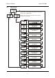
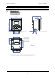
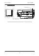
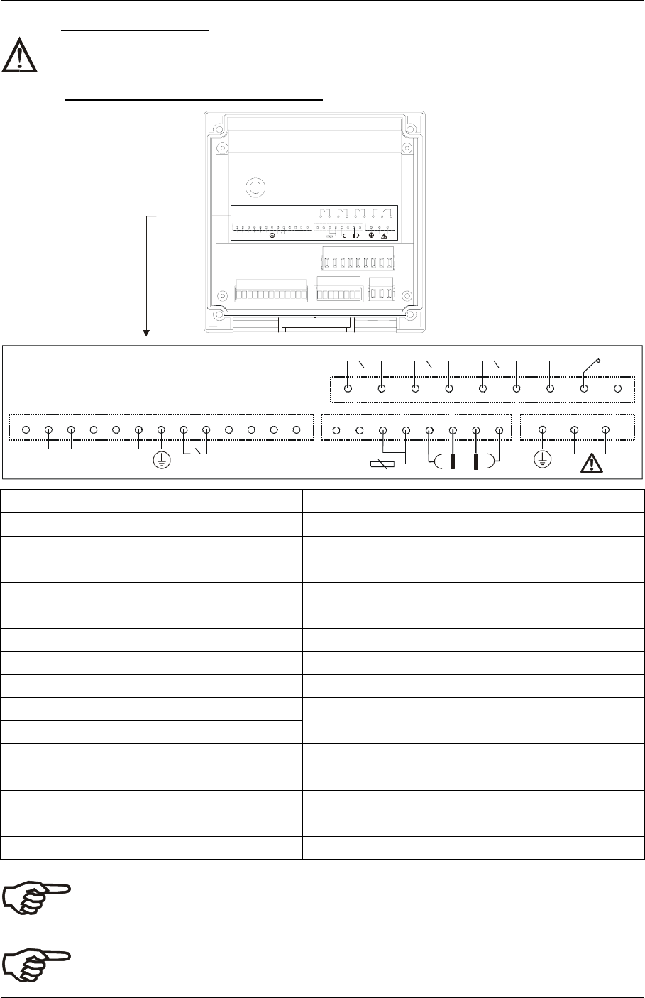
3.2 Connection Diagram
Caution: Ensure electrical mains are disconnected before proceeding.
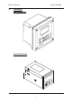
Connections for wall mounting version
RELA RELB WASH RELAY ALARM RELAY
-+
Current
OP 2
29 28 19
GND+12V
-+
Current
OP1
3031 20 22
PT100/
PT1000
2524 26
HOLD
14 13
4
7
65
89
N L
3
12
21
11 10
15
16
17 18
R ELA R ELB WASH R ELAY A LAR M RE LAY
-+
Curre nt
OP 2
29 28 19
GND+1 2V
-+
Curre nt
OP1
3031 20 22
PT10 0/
PT10 00
2524 26
HOLD
14 13
476589
N L
3
12
21
11 10
15 16 17 18
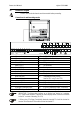
1. AC mains live wire **17. 4 Cell / 2 Cell type Conductivity Input
2. AC mains neutral wire 18. 4 Cell type Conductivity Input
3. AC mains protective earth wire 19. 12V Power supply
4. Relay A (SP 1) 20. 12V ground
5. Relay A (SP 1) 21. no connection
6. Relay B (SP 2) 22. Earth ground
7. Relay B (SP 2) 23. no connection
8. Wash relay 24. Temperature ground
9. Wash relay 25. Temperature input
10. Alarm relay (NC) 26. Temperature sense (short to
11. Alarm relay common terminal 25 if using 2- wire RTD)
12. Alarm relay (NO) 27. no connection
13. Hold function 28. 4-20 mA temperature output, -ve terminal
14. Hold function 29. 4-20 mA temperature output, +ve terminal
15. 4 Cell type Conductivity Input 30. 4-20 mA Conductivity output, -ve terminal
**16. 4 Cell / 2 Cell type Conductivity Input 31. 4-20 mA Conductivity output, +ve terminal
IMPORTANT: The Alarm relay functions as an “Active Low” device i.e. it switches
OFF under Alarm condition. Therefore the Alarm display device should be connected
to the ‘NC’ contacts of the relay (10 & 11).
** When using 2 Cell type Conductivity electrode, terminal 15 should be shorted to
terminal 16 and terminal 18 should be shorted to terminal 17.