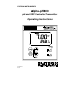
EUTECH INSTRUMENTS αlpha-pH800 pH and ORP Controller/Transmitter Operating Instructions 68X216813 03/99
Preface Thank you for purchasing the αlpha-pH800 series pH/ORP controller/transmitter. This manual serves to explain the use of the αlpha-pH800 series pH/ORP controller/transmitter. The manual functions in two ways, firstly as a step by step guide to help the user operate the instrument. Secondly, it serves as a handy reference guide. This instruction manual is written to cover as many anticipated applications of the αlpha-pH800 pH/ORP controller/transmitter.
TABLE OF CONTENTS 1 INTRODUCTION................................................................................................ 1 1.1 Description of Unit.................................................................................... 1 1.2 Applications................................................................................................ 2 2 ASSEMBLY AND INSTALLATIONS ............................................................. 3 2.1 Measurement and Control System............................
1 1.1 INTRODUCTION Description of Unit Thank you for purchasing Eutech’s ¼ DIN alpha-800 series pH/ORP process controllers. This unit is used for measuring either pH or ORP parameter one at a time, and the operational mode is switchable from the menu. You can use this unit to measure pH or ORP with limit control.
1.2 Applications Use this controller in panel mounted enclosures for applications such as water treatment and monitoring, galvanic-decontamination, chemical processing food processing, clean or waste water control and neutralisation process.
2 2.
3 ELECTRICAL CONNECTIONS 3.
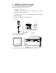
Temp. PE N L pH S 0 / PA 3 1 22 2 21 20 19 18 S BNC Symmetrical high-impedance connections Measuring Cable Potential Matching Pin (PM) pH Combination Electrode Temp.
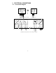
3.2 Back Panel The back panel consists of two connectors. The first connector is the 17-way PCB edge connector and the other is the 5-way connector. Connection for the 17-way screw terminals (from left to right): 1.AC mains live wire 2.AC mains neutral wire 3.AC mains protective earth wire 4.Low set relay resting position (NC) 5.Low set relay common 6.Low set relay working position (NO) 7.High set relay resting position (NC) 8.High set relay common 9.High set relay working position (NO) 10.
Pt100/ Pt1000 0V/ PAL S/ RELAY B NC FUSE 250VAC 100mA (F) RELAY A L N PE 7 NC NC HOLD NC - +
4 OVERVIEW 4.1 Keypad and Display 4.1.1 Keypad • Perform rapid 2-point calibration and view electrode status • Allows entry to Set up mode • Select individual functions within the function group of Set up mode • Store input data in the Set up mode • Start calibration in the calibration mode • Select various function groups in the Set up mode.
Function Groups The main function and sub-function groups are organised in a matrix format for configuration and selection of parameters. The main function groups are: 1) Offset adjustment (OFS) o 2) Temperature Measurement / compensation settings (Set C) 3) Control relay 1 configuration (SP1) 4) Control relay 2 configuration (SP2) 5) Configuration (ConF) 6) Calibration (CAL pH) 4.2 Control Concept The main function and sub-function groups are organised in a matrix format as shown below.
5 MEASUREMENT 5.1 Display in Measurement mode When the controller is initially powered on, it automatically enters into the Measurement mode after the large dual LCD displays all segments briefly. The upper display shows the measured pH or ORP value, while the lower display shows either the temperature value if the controller is set for pH measurement or “OrP” if it is set for ORP measurement.
6 CALIBRATION Direct Calibration from the Measurement mode is possible via the CAL key. The Calibration procedure can also be accessed from the Advanced Setup mode. 6.1 pH Calibration This unit features five preset buffer values (1.00, 4.00, 6.86 or 7.00, 9.00, 9.18 and 10.00) for quick, two-point auto calibration. When calibrating this instrument, standard pH buffer solutions must be used. 1) Enter Calibration mode. While in the SETUP Measurement mode, push the CAL key.
symmetrical mode, immerse the potential matching pin in the buffer. 4) Press the ENTER key to start the calibration at pH 7 (or pH 6.86). The electrode indicator and CAL indicator both flash. The controller automatically adjusts the reading to match the buffer value. 5) The lower display will now show its next lower ‘pH’ buffer. Use ∆ and ∇ keys to select the second buffer from one of the 5 remaining preset values.
6.2 ORP – mV Calibration This mode allows one-point calibration. 1) Enter Calibration mode. While in Measurement mode, push the CAL key. Press the ENTER key. SETUP The upper and lower display reads “CAL OrP”. HOLD CAL OrP Note: If the upper and lower display read “CAL PH”, see section 7.4 for procedures on how to switch from pH to ORP mV readings. CAL 2) Place sensor in the ORP solution. HOLD 3) Press the ENTER key to begin calibration. The 226 mV C “CAL” indicator appears on the display.
7 7.1 ADVANCED SET UP MODE Electrode Offset (OFS) sub-function This option is available only in the pH mode. An allowance of ±120mV is allowed to correct for electrode deviations. This feature is useful for prolonged on-line applications. The controller will add or subtract the value from the measured pH and display the correct value. Should the offset value be too high, consider performing maintenance on the electrode followed by calibration.
7.2 7.2.1 Setting temperature (Set oC) sub-function Selecting automatic or manual temperature compensation 1) Enter Advanced Set-up mode by pressing the ENTER key. 2) Press the ∆ or ∇ keys to scroll until the SETUP o display shows “Set C”. HOLD SEt o C 3) Press the ENTER key. The lower display shows “Atc”; the upper display shows “on” or “oFF” depending on whether or not ATC is selected. SETUP HOLD 4) Press the ∆ or ∇ keys to toggle between on Atc ATC on and off.
4) Press the ∆ or ∇ keys to scroll the lower display to match the correct value. The upper display will now show the offset value. You can offset temperature up to ± 5 C. o 5) Press the ENTER key to confirm your selection. 6) Continue with additional Advanced Set-up procedures, or return to the Measurement mode by pressing the ∆ and ∇ keys (escape) simultaneously. 7.2.3 Setting manual temperature compensation Note: This option is not available when the controller is set for ATC operation.
5) Press the ∆ or ∇ keys to adjust the calibration temperature value, o between –9.9 and 125 C. 6) Press the ENTER key to confirm. 7) Continue with additional Advanced Set-up procedures, or return to Measurement mode by pressing the ∆ and ∇ keys (escape) simultaneously.
7.3 Control Relay A/Control Relay B (SP1/SP2) sub- function The SP1 option sets the operating parameters for Relay A; the SP2 option sets the operating parameters for relay B. Since these groups have the same set-up parameters, they are described together. 7.3.1 Entering the Set point 1 (Set point 2) sub-function 1) Enter Advanced Set-up mode. Push the SETUP HOLD SP1 ENTER key. 2) Press the ∆ or ∇ keys to scroll until the upper display shows SP1 (SP2). SETUP HOLD 4.00 SP1 pH 7.3.
1) Follow directions in 7.3.1 to enter Control Relay mode. 2) Press the ENTER key until the upper display shows Lo or Hi and the lower display shows SP1 (SP2). 3) Press the ∆ or ∇ keys to select low (lo) or high (hi) set point for SP1 (SP2). 4) Press the ENTER key to confirm. 5) Proceed to 7.3.4 step 3, or return Measurement mode by pressing the ∆ and ∇ keys simultaneously (escape). 7.3.
5) Proceed to 7.3.5 step 3, or return to Measurement mode by pressing the ∆ and ∇ keys simultaneously (escape). NOTE: Please refer to Appendix 3 for a graphical representation of the Hysteresis. 7.3.5 Setting an on-delay time lag You can set as time delay for each relay, which stops the relay from switching on the moment the set point is exceeded. This controller lets you set a 0 to 2000 second time delay before the relay activates. 1) Follow directions in 7.3.1 to enter Control SETUP HOLD 0 On.
3) Press the ∆ or ∇ keys to enter off-delay time for Set point 1 (Set point 2). The controller will delay activation for the number of seconds (0 to 2000) you select. 4) Press the ENTER key to confirm your selection. 5) Continue with Advanced Set-up mode procedures, or return to Measurement mode by pressing the ∆ and ∇ keys simultaneously (escape).
7.4 Configuration (ConF) sub-function The options available in this sub-function allows the controller to be configured as a pH or ORP controller. 7.4.1 Entering the Configuration sub-function 1) Enter Advanced Set-up mode. Press the ENTER key. 2) Press the ∆ or ∇ keys to scroll until the upper display shows “ConF”. 7.4.
7.4.3 Reverting to factory default settings Use this parameter to reset all settings to factory default. Changing from “no” to “YES” and pressing the ENTER key resets all settings to factory default. WARNING: If “Yes” is selected, all settings input SETUP will be overwritten! HOLD 1) Follow directions in 7.4.1 to enter Configuration mode. no dEF 2) Press the ENTER key. Scroll with the ∆ or ∇ keys until the upper display shows “no” or” YES”, and the lower display shows “deF” (default).
8 TECHNICAL SPECIFICATIONS pH Range Resolution Relative Accuracy mV Range Resolution Relative Accuracy Temperature Resolution Relative Accuracy Sensor Temperature Compensation Set-point and Controller Functions Function (switchable) Controller characteristics Pickup / Dropout delay Switching pH hysteresis Switching ORP hysteresis Contact outputs, controller Switching voltage Switching current Switching power Electrical Data and Connections Power Requirements Frequency Signal Output Load pH / ORP input Conn
9 ACCESSORIES Product Description Code no.
10.3 Return of Goods Authorisation must be obtained from Eutech Instruments’ Customer Service Dept. to issue a RGA (Return of Goods Authorisation) number before returning items for any reason. When applying for authorisation, please include data requiring the reason of return. Items must be carefully packed to prevent damage in shipment and insured against possible damage or loss. Eutech Instruments will not be responsible for any damage resulting from careless or insufficient packing.
11 APPENDICES 11.1 Appendix 1 Jumper Positions - Internal to the controller JP 1 Selects the input voltage 220 VAC. JP 2 Selects the input voltage 110 VAC. JP 3 Solder bridge selects between Pt100 and Pt1000. Fuse Note that there is a fuse (slow-blow 100mA) internal to the controller. Before opening the unit, ENSURE that the power cable is physically separated from the power supply. Replace fuse with the recommended type only.
11.2 Appendix 2 The following table shows the various pH values at different temperature of the solution during calibration. Temperature (oC) pH 1.68 (oxalate) pH 4.01 (phthalate) pH 6.86 (tetraoxalate) 0 5 10 15 20 25 30 35 40 45 50 55 60 70 80 90 1.67 1.67 1.67 1.67 1.68 1.68 1.69 1.69 1.70 1.70 1.71 1.72 1.73 1.74 1.77 1.80 4.01 4.01 4.00 4.00 4.00 4.01 4.01 4.02 4.03 4.04 4.06 4.08 4.10 4.12 4.16 4.20 6.98 6.95 6.92 6.90 6.88 6.86 6.85 6.84 6.84 6.83 6.83 6.83 6.84 6.85 6.86 6.88 28 pH 7.
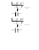
11.3 Appendix 3 Simple Explanation on the Function of Hysteresis SP1 Set to LO SP2 Set to HI RELAY ON RELAY OFF 4.0 4.5 7.0 9.5 10.0 SP2 SP1 FORWARD DIRECTION HYSTERESIS BAND (DEFAULT = 0.5 pH) REVERSE DIRECTION The controller relay activates when the set-point is reached. In the reverse direction, it does not de-activate when the value reaches the set-point. Instead, it continues to be active till the value reaches the amount set by the Hysteresis band.
CALIBRATION RECORD Calibration Date Electrode Slope Electrode Offset