4
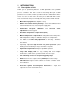
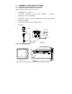
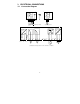
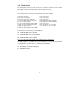
3 ELECTRICAL CONNECTIONS
3.1 Connection Diagram
Signal OutputHold Input
Relay B
Relay A
Po
er Mains
pH
m
-
+
PE/S
PE
AC:
NL
1
2
5
4
36
78 9
10
11
12 13
14
15
17
15
16
* ) indicated contact positions are for currentless conditions
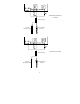
Pt 100
Potential Matching Pin (PMP)
Signal Input pH/ORP
S/
V
PE/S
pH
18 19 20 21 22
S/S/
BNC