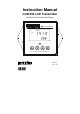
Instruction Manual CON 500 LCD Transmitter Conductivity Transmitter with Display lpha CON500 MEAS READY 1413 . µS °C ATC 2-wire Conductivity Transmitter 68X216867 Technology Made Easy ...
Preface This manual serves to explain the use of the CON 500 transmitter. It functions in two ways, firstly as a step by step guide to help you to operate the transmitter. Secondly, it serves as a handy reference guide. It is written to cover as many anticipated applications of the transmitter as possible. If there are doubts in the use of the transmitter, please do not hesitate to contact the nearest Authorized Distributor.
TABLE OF CONTENTS 1 INTRODUCTION ................................................................................... 1 2 PREPARATION .................................................................................... 2 2.1 POWER SUPPLY REQUIREMENTS (SL2 POSITION)........................................... 3 2.2 CONNECTING THE ELECTRODE AND TEMPERATURE SENSOR (SL1 POSITION) .... 3 2.2.1 To connect the Conductivity electrode: ............................................. 3 2.2.
9 SPECIFICATIONS .............................................................................. 25 10 ACCESSORIES............................................................................... 26 11 WARRANTY .................................................................................... 27 12 RETURN OF ITEMS ........................................................................
Instruction Manual 1 CON 500 INTRODUCTION Thank you for selecting a CON 500 LCD Transmitter. This isolated output 4-20mA transmitter is a sturdy microprocessor-based instrument that measures conductivity and temperature and transmits its output via the 2-wire power supply loop. This transmitter has many user-friendly features – all of which are completely accessible through the water-resistant membrane keypad. Your transmitter includes an instruction manual and a warranty card.
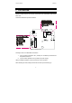
Instruction Manual 2 CON 500 PREPARATION Remove screws from the four corners at the back of the Transmitter, and remove back cover. Connectors should be exposed as follows: NC NC NC Figure 1 – Connection Guide All wiring is done on 2 detachable connectors: – 1. 9-pin connector (located on SL1 position) for Conductivity electrode and temperature sensor; & 2. 3-pin connector (located on SL2 position) for power supply. Using a suitable screwdriver, loosen screws from top of connector.
Instruction Manual 2.1 CON 500 Power Supply Requirements (SL2 Position) The CON 500 transmitter requires a 12 to 24V DC power supply. Other Transmitters and/or a chart recorder may be connected in the loop. 1. Insert positive loop wire from power supply to pin 1, tighten screw. 2. Insert negative loop wire to pin 2, tighten screw. This wire may be linked to a chart recorder or to negative terminal of power supply. Alpha CON 500 1 Power Supply 2 Chart Recorder 2.
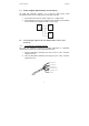
Instruction Manual 2.2.2 CON 500 To connect ATC temperature sensor: For Automatic Temperature Compensated (ATC) Conductivity readings, an in-built temperature sensor is usually integrated in the industrial conductivity electrodes. Otherwise, a separate 100Ω Pt RTD temperature probe can be used. 3 wire temperature sensor 1. Insert the Pt100 input wire to pin 5 of SL1 connector. Tighten the screw. 2. Insert the Pt100 sense wire to pin 6 of SL1 connector. Tighten the screw. 3.
Instruction Manual 3 3.1 CON 500 INSTALLATION Mechanical Dimensions lpha CON500 2-wire Conductivity Transmitter 3.
Instruction Manual 3.3 CON 500 Panel Mount 1. Prepare panel cut-out of 92.0 mm by 92.0 mm Panel (side) 2. Remove back cover of transmitter and slide it through panel cut-out 4. Thread rods through lugs until transmitter is held in place against panel 3.
Instruction Manual 4 4.1 CON 500 DISPLAY AND KEYPAD FUNCTIONS Display The LCD has a primary and secondary display. • The primary display shows the measured conductivity value. • The secondary display shows the measured temperature. In Calibration mode, measured conductivity values are displayed here. Primary Display (Upper Display) 16 15 14 1 2 SETUP MEAS 4 3 CAL R. % -.8.8.8 ON mS µS 5 6 7 K= -1.8.8.8 ERR 13 12 11 10 8 °C ATC 9 Secondary Display (Lower Display) 1.
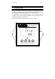
Instruction Manual 4.2 CON 500 Keypad lpha CON500 MEAS READY 1413 . µS °C ATC 2-wire Conductivity Transmitter The four-button keypad allows easy and quick operations of the Transmitter. Key CAL Function Brings you directly into the Calibration mode. If you were in Conductivity Measurement mode, press CAL to enter Conductivity Calibration mode.
Instruction Manual 5 5.1 CON 500 CALIBRATION Important Information on Transmitter Calibration Calibration should be carried when you are using your transmitter with a new electrode for the first time or when you suspect that the transmitter/electrode is out of calibration. Your transmitter allows you to perform temperature calibration and conductivity calibration.
Instruction Manual CON 500 Table 1 Conductivity Measuring Range Recommended Calibration Solution Range 0.00 Æ 19.99 µS 6.00 to 17.00 µS 0.0 Æ 199.9 µS 60.0 to 170.0 µS 0 Æ 1999 µS 600 to 1700 µS 0.00 Æ 10.00 mS 6.00 to 7.00 mS 0.00 Æ 19.99 mS 6.00 to 17.00 mS 0.0 Æ 199.9 mS 60.0 to 170.0 mS To view current calibration point, see Section 6.8 - Viewing Calibration . Do not reuse calibration solutions after calibration.
Instruction Manual 5.2 CON 500 Temperature Calibration You need to perform temperature calibration if your transmitter temperature reading is inaccurate or if the transmitter’s cell constant setting is changed. It is because the transmitter’s temperature offset calibration will be erased once a new cell constant is selected.
Instruction Manual 5.3 CON 500 Conductivity Calibration MEAS A 1-point Calibration is required for this transmitter. If the calibration process is aborted, your transmitter will revert to the previous calibration data. 1. Organize your calibration standard solution in two beakers – one for rinsing and the other for calibration. Prepare separate deionized water for electrode rinsing. 2. Rinse the electrode in de-ionized water and then rinse with the calibration standard. 3.
Instruction Manual 6 CON 500 ADVANCED SETUP FUNCTIONS The advanced setup mode lets you customize your transmitter’s preferences and defaults. This transmitter features different sub groups that organize all setup parameters. The sub-groups are: 6.1 Range and Zooming Selection Setting Your CON 500 transmitter provides six selections of conductivity measurement ranges to suit your process application needs.
Instruction Manual 4. 5. 6. CON 500 For zooming setting, use the ▲ or ▼ keys to set the conductivity low zoom value for the 4 mA current and press the ENT key to confirm. The transmitter now displays the high zoom value setup. Use the ▲ or ▼ keys again to set the conductivity high zoom value for the 20 mA current and press the ENT key to confirm and return to the range setup mode. Press both ▲ and ▼ keys together to return to the measurement mode. - 14 - SETUP HOLD 0.00 µS L SETUP HOLD 19.
Instruction Manual 6.2 CON 500 Temperature Compensation Setting Conductivity readings are affected by temperature. Under varying temperature conditions, use ATC to compensate for the conductivity values. If temperature of sample is constant, and a temperature sensor/probe is not available, Manual Temperature Compensation can be utilized. 6.2.1 Automatic Temperature Compensation For automatic temperature compensation (ATC) selection, connect the ATC sensor to the transmitter, as described in Section 2.
Instruction Manual 6.2.2 CON 500 Manual Temperature Compensation For manual temperature compensation you can set the process and calibration temperatures. This allows calibration at a temperature other than the process temperature. Example: setting a calibration temperature of 25°C lets you calibrate using standard solutions at 25°C, even if your process temperature is different from 25°C. From the measurement mode, o 1. Press the ENT key and use ▲ or ▼ keys to select ‘SEt C’. 2.
Instruction Manual CON 500 SETUP HOLD SETUP SETUP HOLD HOLD SETUP SETUP HOLD . . HOLD °C . ATC SETUP HOLD .
Instruction Manual 6.3 CON 500 HOLD Current Setting SETUP When Transmitter is in CAL or SETUP modes, it automatically goes into a ‘HOLD’ mode. HOLD To indicate Transmitter is in ‘HOLD’ mode, output current can be set to 22 mA output by activating the ‘HLD On’. 1. Press the ENT key and use ▲ or ▼ keys to scroll till LCD displays ‘SEt’ in the upper display; and ‘HLd’ in the lower display. Press the ENT key again. 2. Upper display now shows ‘HLd’. Lower display will show either ‘OFF’ or ‘On’.
Instruction Manual 6.5 CON 500 Temperature Coefficient and Normalization Temperature Setting Since different process liquid may require different temperature coefficient factor for its temperature compensation calculation, CON 500 transmitter allows 0 to 10% temperature coefficient factor adjustment to cater for your different application needs. You also have the selection of 25.0 °C or 20.0°C for the conductivity measurement normalization temperature. 6.5.
Instruction Manual 6.6 CON 500 Cell Constant Setting You can select up to three types of cell constant in the setup mode: - K=1.0, K=0.1 or K=10. From the measurement mode, 1. SETUP Press the ENT key to enter the setup mode. Use the ▲ or ▼ keys to scroll till LCD displays ‘SEt’ in the upper display; and ‘CEL’ in the lower display. 2. Press the ENT key to enter the cell constant setup page. 3. Use the ▲ or ▼ keys to select the desired cell constant and press the ENT key to confirm the selection.
Instruction Manual 6.8 CON 500 Viewing Calibration Point This mode lets you view the current calibration point and its range. From the measurement mode of a selected measuring range, SETUP CAL CAL HOLD 1. Press the ENT key to enter the setup mode. Use the ▲ or ▼ keys to scroll till LCD displays ‘CAL’ in the upper display. 2. Press the ENT key to enter the calibration point viewing page. The display will show the current calibration point and its range. 3. SETUP 12.
Instruction Manual CON 500 6.10 Reset Function SETUP The reset function lets you choose to either reset the transmitter’s conductivity calibration only or conductivity calibration plus all setup functions that you might have changed back to factory default settings. However, the temperature compensation setting, as in Section 6.2, will remain unchanged. From the measurement mode, 1. 2. HOLD SETUP Press the ENT key to enter the setup mode.
Instruction Manual 7 CON 500 FACTORY DEFAULT SETTINGS SETUP PAGE FUNCTION SET rng Selection of effective conductivity range Setting low zooming selection Setting high zooming selection SET °C Selection of Automatic or Manual Temperature Compensation DEFAULT SETTING 1999 uS, r3 0 uS, Lo 1999 uS, Hi AtC On SET HLd Selection of HOLD current to be of 22 mA or the last current output value HLd OFF SET org Selecting Out of Range current output to be constant 3.
Instruction Manual 8 CON 500 TROUBLE SHOOTING GUIDE Problem Cause Solution Power on but no display a). Loose connections a). Ensure cables are making good contact. Unstable conductivity readings b). Cables not in correct polarity (+ and – position). a). Air bubbles in probe. b). Dirty probe. b). Re-wire loop cables with correct polarity. a). Tap probe to remove bubbles. c). Probe not deep enough in sample. b). Clean probe and recalibrate. Oscillating temperature readings a).
Instruction Manual 9 CON 500 SPECIFICATIONS Cell Constant Conductivity Range Resolution (K) (r1 to r6) 0.1, 1.0 Range 1 = 0 – 19.99 uS/cm 0.01 uS 0.1, 1.0, 10.0 Range 2 = 0 – 199.9 uS/cm 0.1uS 0.1, 1.0, 10.0 Range 3 = 0 – 1999 uS/cm 1 uS 0.1, 1.0, 10.0 Range 4 = 0 – 10.00 mS/cm 0.01 mS 0.1, 1.0, 10.0 Range 5 = 0 – 19.99 mS/cm 0.01 mS 1.0, 10.0 Range 6 = 0 – 199.9 mS/cm 0.1 mS o Temperature Range 0-100 C Temperature Resolution 0.1 C Temperature Relative Accuracy ± 0.
Instruction Manual CON 500 10 ACCESSORIES Replacement Unit Product Description Eutech Instruments Order Code CON 500 LCD Transmitter EC-CONCTP0500 Assembly Accessories Product Description Eutech Instruments Order Code Conductivity cell, Epoxy body, Graphite sensor, w/3-wire Pt100, k = 0.1 ECCONSEN89X Conductivity cell, Epoxy body, Graphite sensor, w/3-wire Pt100, k = 1.0 ECCONSEN88X Conductivity 2 Cell type probe, 0.1 - 200µS; Cell constant, K=0.
Instruction Manual CON 500 11 WARRANTY This transmitter is supplied with a one-year warranty against significant deviations in material and workmanship from date of purchase and a six-month warranty for probe. Each instrument will have a warranty card with a specific serial number. The warranty card must be endorsed by the Authorized Distributor at the point of sale.
For more information on our products, contact your nearest distributor or visit our website listed below: Eutech Instruments Pte Ltd. Blk 55, Ayer Rajah Crescent, #04-16/24 Singapore 139949 Tel: (65) 6778 6876 Fax: (65) 6773 0836 E-mail: marketing@eutechinst.com Web-site: www.eutechinst.