
Instruction manual

22
5.4 Relay 1/Relay 2 Settings
NOTE:
If controller type is set to ‘OFF’ (Refer section 5.5 for controller
settings), the ‘Relay 1/Relay 2 Setting’ is not available.
The SP1 settings determine the operating parameters for Relay 1; while SP2
settings define the operating parameters for Relay 2. Since these two settings have
identical setup parameters, only SP1 is described here.
Note that when you change measuring range of the controller, the values you have
set for SP1 & SP2 will not be affected. However, the unit of measurement &
resolution displayed in LCD for SP1 & SP2 will change according to the newly
selected measuring range.
SETUP
HOLD
1
ENT
SETUP
HOLD
2
ENT
SETUP
HOLD
SETUP
HOLD
3
3
ENT
ENT
SETUP
HOLD
4
ENT
SETUP
HOLD
SETUP
HOLD
ENT
ENT
5
6
µS
µS
µS
µS
11
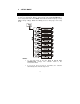
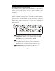
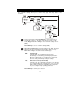
From measurement mode press ENT key to enter setup mode as
described in section 5.1. The LCD shows the first screen of setup mode
(rAng). Press ▲ or ▼ key to select relay 1 (Set point 1) settings
screen (SP1).
Press ENT key to access relay 1 settings (SP1).
2
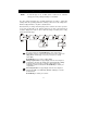
Setting set point value: The upper display shows the last configured
set point value, otherwise the default value 100 µS. Press ▲ or ▼ key
to enter the value for set point 1, at which control function of the
conductivity controller should activate. Press ENT key to confirm your
set point value.
3
Select relay function: The upper display shows the last configured
relay function (LO = Low or HI=High). Press ▲ or ▼ key to select the
desired function.
Press ENT key to confirm your selection.