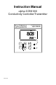
Instruction Manual αlpha-CON1000 Conductivity Controller/Transmitter Conductivity Controller α lpha CON1000 MEAS 8.08 25.
Preface This manual serves to explain the use of the αlpha-CON1000 series Conductivity controller/transmitter. The manual functions in two ways: firstly as a step by step guide to help the user operate the instrument. Secondly, it serves as a handy reference guide. This instruction manual is written to cover as many anticipated applications of the αlpha-CON1000 Conductivity controller/transmitter.
Operating Instructions αlpha-CON1000 7.4 Controller (Cntr) sub-function............................................................... 19 7.5 Measurement Range sub-function ......................................................... 20 7.6 Current Output (rng) sub-function......................................................... 21 7.7 Configuration (ConF) sub-function ....................................................... 22 7.8 Calibration (CAL) sub-function ..............................................
• • • • • • • Three control modes: limit, proportional pulse length or proportional pulse frequency Large dual display LCD for easy reading with clear multiple annunciators, alarm status and operational message annunciators Two switching contacts as set-point triggering relays and an alarm output relay Separate alarm relay alerts you when set points have exceeded the limits and if the Pt100/Pt1000 wires are broken or disconnected during the ATC function Hold function freezes output current (0/4...
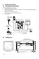
2 Assembly and Installation 2.1 Measurement and Control System A typical measurement system consists of: • a αlpha-CON1000 process controller • a suitable Conductivity electrode with the appropriate Cell constant and integrated temperature sensor Pt 1000 or Pt 100, • an immersion, flow or process assembly • a final control element such as pump or valve and • a chart recorder.
The field-tested control panel housing is 96 x 96 mm; with protection class IP 54 (front). Electrical Connection 3.
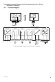
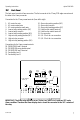
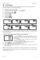
αlpha-CON1000 Operating Instructions 3.2 Back Panel The back panel consists of two connectors. The first connector is the 17-way PCB edge connector and the other is the 5-way connector. Connection for the 17-way screw terminals (from left to right): 1. 2. 3. 4. 5. 6. 7. 8. 9.
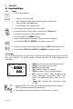
4 Overview 4.1 Keypad and Display 4.1.1 Keypad • Perform rapid calibration • • • • Allows entry to Set up mode Select individual functions within the function group of Set up mode Store input data in the Set up mode Start calibration in the calibration mode • Select various function groups in the Set up mode.
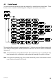
αlpha-CON1000 Operating Instructions 4.2 Function Groups The main function and sub-function groups are organised in a matrix format for configuration and selection of parameters.
4.3 Control Concept The main function and sub-function groups are organised in a matrix format as shown below. These functions can be accessed via the front keypad for configuration and selection of parameters. The controller offers two levels of password protection: (1) for direct access to calibration function and (2) for setting or editing specific controller parameters or functions in the SETUP mode to suit individual requirements.
αlpha-CON1000 Operating Instructions 5 MEASUREMENT 5.1 Display in Measurement mode When the controller is initially powered on, it automatically enters into the Measurement mode after the large dual LCD displays all segments briefly. The upper display shows the measured Conductivity value, while the lower display shows the temperature value. Annunciators at the right side of the display indicate whether the controller is set for µS or mS measurement.
NOTE: To view (not change) the SETUP parameters, push the ENTER key when the security code reads “000”.
Operating Instructions αlpha-CON1000 5.2.1.1 Clearing the Calibration security code from the display The calibration security code automatically resets from “11” to “000” after you return to Measurement mode, so you do not need to clear the security code from the display. 5.2.2 How to enter and change parameters in Advanced Setup mode 1) Press the ENTER key once. The upper display shows “000” and the lower display shows “S.Cd” to prompt you to enter the Advanced Setup security code.
6 Calibration Mode You can reach the Calibration mode directly from the Measurement mode by pressing the CAL key and entering the Calibration security code. You can also reach the Calibration mode from the Advanced Setup mode. 6.1 Conductivity Calibration Calibration is always carried out in the specific range selected. The Conductivity Controller allows a one-point calibration. HOLD SETUP CAL 6 Con HOLD CAL 100.0 100.0 6 HOLD CAL 1413 6 25.0 HOLD µS o C ATC CAL 100.0 100.
7 7.1 ADVANCED SET-UP MODE Temperature Coefficient sub-function This sub-function allows you to select the correct temperature coefficient for optimum operations. For applications in the pure water or ultr-pure water industries, simply select the “Pur” temperature coefficient option. For all other applications, select “Lin” temperature coefficient. The controller allows further input of temperature coefficient values, independently for the process and for the calibrating solutions. Default is at 2.10 %.
7.2 Temperature calibration (ATC mode only) HOLD SETUP on Atc HOLD SETUP 0.0 o C 25.0 7.2.1 ATC 1) Select “ATC on” as described above in Section 7.4.1. 2) Press the ENTER key. The upper display indicates the current temperature offset. The current measured temperature is shown in the lower display. 3) Compare the current measured temperature on the controller display to a thermometer known to be accurate. Note down the correct temperature value.
αlpha-CON1000 Operating Instructions 7.3 Control Relay A/Control Relay B (SP1/SP2) sub-function The SP1 option sets the operating parameters for Relay A; and SP2 for relay B. Since these groups have the same set-up parameters, they are described together. HOLD SETUP HOLD SETUP SP 1 7.3.1 HOLD SETUP 100 SP 1 HOLD SETUP Lo SP 1 HOLD SETUP 20 HYS HOLD SETUP 0 On.d 0 Of.d Entering the Set point 1 (Set point 2) sub-function 1) Enter Advanced Set-up mode.
Example: You have set your set point 1 (Lo) at 6.00 µS and your hysteresis limit value is at 0.50 µS. If your measured value undershoots the low set point of 6.00 µS, the controller’s relay activates, which in turn activates an external device such as a pump or valve. The actions of the external device will cause the value to rise above 6.00 µS. When the value has increased to 6.50 µS, the relay, and hence the pump will switch off. HOLD SETUP 1) Follow directions in 7.5.3 to enter Control Relay mode.
αlpha-CON1000 Operating Instructions 7.4 Controller (Cntr) sub-function You can set the controller’s parameters in this sub-function. 7.4.1 Entering the Controller sub-function 1) Enter Advanced Set-up mode. Push the ENTER key and scroll to Advanced set-up security code “22”. Push the ENTER key again. 2) Press the ∆ or ∇ keys to scroll until the upper display shows “Cntr”. HOLD SETUP Cntr HOLD SETUP L.Ct tyP HOLD SETUP dEEn rEL HOLD SETUP oFF tyP 7.4.
7.4.3 Choosing break/make contact relay type Note: If the controller type “oFF” is set, the parameters listed in 7.5.3, 7.5.4, 7.5.5 and 7.5.6 are blanked out. This mode lets you determine the relay-state under Non-Alarm condition – dEEN (de-energised) or EN (energised). 1) Follow directions in 7.6.2 to enter Controller mode. HOLD SETUP 2) Press the ENTER key. Scroll until the lower display shows “rEL” and the upper display shows the current selection (de-energised = rEL dEEN or energised = EN).
αlpha-CON1000 Operating Instructions 7.6 Current Output (rng) sub-function This sub-function lets you set the transmitter current output range of this unit. The difference between the upper and lower range has to be a minimum of 20% of Full Scale, anywhere on the scale. 7.6.1 Entering current output sub-function HOLD SETUP 1) Enter Advanced Set-up mode. Push the ENTER key and scroll to Advanced Set-up security code “22”. Push the ENTER key again.
8) 9) Press the ENTER key to confirm your selection. Press the ENTER key to return to Advanced Set-up mode, or return to Measurement mode by pressing the ∆ and ∇ keys simultaneously (escape). HOLD SETUP COnf HOLD SETUP HOLD SETUP 0 ALd Stdy HOLD SETUP 0.0 ALC L.Ad HOLD SETUP no 7.7 Configuration (ConF) sub-function dEF This group of parameters lets you configure the controller to suit your requirements. 7.7.1 Entering the Configuration sub-function 1) Enter Advanced Set-up mode.
αlpha-CON1000 Operating Instructions 1) HOLD SETUP HOLD SETUP Follow directions in 7.9.2 to enter Configuration mode. AL.C 2) Press the ENTER key. Scroll with the ∆ or ∇ keys until the upper display shows “Stdy” or “FLEt” and lower display shows “AL.C.”. AL.C = alarm contact StdY = steady contact FLEt = fleeting (single pulse) contact FLEt 3) Press the ∆ or ∇ keys to select steady or pulse contact. 4) Press the ENTER key to confirm your selection. 5) Proceed to 7.9.
7.8.1 Entering Calibration mode from Advanced Set-up mode 1) Enter Advanced Set-up mode. Push the ENTER key and scroll to Advanced Set-up security code “22”. Push the ENTER key again. 2) 3) 8 Press the ∆ or ∇ keys to scroll until the upper display shows “CAL”. See section 6 for complete calibration procedures. Auto/Manual Mode Regardless of the mode, you can control devices connected to Relay A or Relay B from the front panel of this controller.
αlpha-CON1000 Operating Instructions 9 Technical Specifications Conductivity Range 0.000 to 1.999 µS/cm 0.00 to 19.99 µS/cm 0.0 to 199.9 µS/cm 0 to 1999 µS/cm 0 to 5000 µS/cm 0.00 to 19.99 mS/cm 0.0 to 199.9 mS/cm Resolution 0.001 µS/cm 0.01 µS/cm 0.1 µS/cm 1 µS/cm 5 µS/cm 0.01 mS/cm 0.
10 Accessories Assembly Accessories Product Description Code no. Conductivity Cell, up to 20µS; Cell constant, K=0.01 with integrated Pt 100, EC-CS10-0-01S Material SS316 and 25ft cable (open-ended) Conductivity Cell, up to 20µS; Cell constant, K=0.01 with integrated Pt 100, EC-CS10-0-01T Material Titanium and 25ft cable (open-ended) Conductivity Cell, 0.1 - 200µS; Cell constant, K=0.
Operating Instructions αlpha-CON1000 12 Appendices 12.1 Appendix 1 – Jumper Positions Jumper Positions - Internal to the controller JP 1 Selects the input voltage 220 VAC. JP 2 Selects the input voltage 110 VAC. JP 3 Selects the temperature sensor for Pt1000/Pt100 Fuse Note that there is a fuse (slow-blow 100mA) internal to the controller. Before opening the unit, ENSURE that the power cable is physically separated from the power supply. Replace fuse with the recommended type only.
12.2 Appendix 2 – Measurement Ranges available in the Controller Range No. 1 2 3 4 5 6 7 8 9 0 12.3 Range 0.000 – 1.999 µS 0.00 – 19.99 µS 0.00 – 19.99 µS 0.0 – 199.9 µS 0.0 – 199.9 µS 0 – 1999 µS 0 – 5000 µS 0.00 – 19.99 mS 0.0 – 199.9 mS 0.0 – 199.9 mS Resolution 0.001 µS 0.01 µS 0.01 µS 0.1 µS 0.1 µS 1 µS 5 µS 0.01 mS 0.1 mS 0.1 mS Appendix 3 – Conductivity at Related Temperature Coefficients (25oC) Substance Concentration wt % Conductivity 10-4 S/cm NaOH 5 10 15 20 30 40 25.2 29.4 33.6 42.0 0.
Substance Concentration wt % Conductivity 10-4 S/cm H3PO4 (15oC) 10 20 40 45 50 5 10 15 20 25 5 10 15 5 10 20 30 40 5 10 20 40 50 60 80 100.14 5 10 20 30 1 10 15 20 30 40 5 10 15 5 10 15 20 566 1129 2070 2087 2073 672 1211 1642 1957 2153 409 687 886 1969 3124 3463 662 5152 2085 3915 6527 6800 54055 3726 1105 187 109 189 320 421 5.84 15.26 16.19 16.05 14.01 10.81 456 705 836 690 1359 2020 2677 NaCl Na2SO4 HCl H2SO4 CuSO4 CH3COOH Na2CO3 KCl 68X216802 Conductivity Coefficient 1.04 1.14 1.50 1.
Substance KBr (15oC) KCN (15oC) NH4Cl (NH4)2SO4 12.4 25 Concentration wt % 2810 Conductivity 10-4 S/cm 1.66 Conductivity Coefficient 5 10 20 3.25 6.5 5 10 15 20 25 5 10 20 30 465 928 1907 507 1026 918 1776 2586 3365 4025 552 1010 1779 2292 2.06 1.94 1.77 2.07 1.93 1.98 1.86 1.71 1.61 1.54 2.15 2.03 1.93 1.
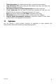
12.5 Appendix 5 - Simple Explanation on the Function of Hysteresis SP1 Set to LO SP2 Set to HI RELAY ON RELAY OFF 10.0 10.5 SP1 FORWARD DIRECTION 100.0 100.5 mS SP2 HYSTERESIS BAND REVERSE DIRECTION The controller relay activates when the set-point is reached. In the reverse direction, it does not deactivate when the value reaches the set-point. Instead, it continues to be active till the value reaches the amount set by the Hysteresis band.
12.