
Instruction manual

68X216802
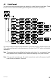
4 Overview
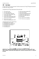
4.1 Keypad and Display
4.1.1 Keypad
• Perform rapid calibration
• Allows entry to Set up mode
• Select individual functions within the function group of Set up mode
• Store input data in the Set up mode
• Start calibration in the calibration mode
• Select various function groups in the Set up mode.
• Set parameters and numerical values in sub functions of Set up mode
If pressed continuously, the setting speed increases
• Control the relays in the MANUAL function
• Return to the Measurement mode when both keys are pressed together
• Switch between AUTO and MANUAL relay operation using a code
• Display limit set-point values for the switch contacts in AUTO relay operation mode
• Switch between RELAY A and RELAY B in MANUAL relay operation mode
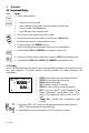
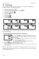
4.1.2 Display
The LCD display features two numerical displays that show status messages and measured values for
easy, quick reference. The display provides short-text information for setting parameters and
configuration.
• HOLD: Relay position and current output are frozen
• SETUP: Set-up mode of function groups
• MEAS: Measurement mode
• CAL: Calibration mode of Conductivity
• READY: Comes on after a successful calibration
•
ATC: Comes on in the ATC mode. Disappears in the
Manual temperature Compensation mode. “ATC”
flashes if the temperature probe is faulty in its ATC
mode
•
Range No.: Indicates the measurement range
selected
• Display for RELAY A/B. Green LED indicates measured value within limit while
RED LED indicates measured value outside limit.
• Alarm display if limit value overshoot or the ATC connection is broken.
-8.8.8.8-8.8.8.8
1.8.8.81.8.8.8 ATC
HOLD SETUP MEAS CAL
READY
µµ
S
mS
o
C
88