Alpha pH 560 pH Controller pH/mV/ºC meter
Preface This manual serves to explain the use of the Thermo Scientific Alpha pH 560 Controller. The manual functions in two ways, firstly as a step by step guide to help the user operate the instrument. Secondly, it serves as a handy reference guide. This instruction manual is written to cover many anticipated applications of the Alpha pH 560 Controller. If you have doubts in the use of the instrument, please do not hesitate to contact the nearest Authorised Distributor.
Contents Chapter 1 Introduction ..................................................................................................... 1 Before You Begin .............................................................................. 1 Intended Use..................................................................................... 1 Safety Instructions............................................................................. 1 Taking Out of Service ........................................................
For NIST Buffer .......................................................................... 20 1-Point Calibration: .................................................................. 20 2-Point Calibration: .................................................................. 20 ORP Calibration............................................................................. 22 Temperature Calibration................................................................. 23 Chapter 5 Setup Mode ..........................
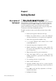
Chapter 1 Introduction Before You Begin Thank you for purchasing the Alpha pH 560 Controller. The construction of the pH 560 Controller employs leading edge technology and complies with safety regulations currently in force. Notwithstanding this, improper use could lead to hazards for the user or a third-party, and/or adverse effects on the plant or other equipment. Therefore, the operating instructions must be read and understood by the persons involved before working with the pH Controller.
Taking Out of Service Correct Disposal of the Unit 2 • The Alpha pH 560 must only be operated under the specified operating conditions (see Page 36). • The Alpha pH 560 must not be repaired by the customer. • No modifications to the Alpha pH 560 are allowed. The manufacturer/supplier accepts no responsibility for damage caused by unauthorized modifications. The risk is borne entirely by the user. • First disconnect the unit from the power supply and then undo all electrical connections.
Chapter 2 Getting Started Description of Instrument The Thermo Scientific Alpha pH 560 Controller is used for measuring pH and temperature values. The pH values can be measured using industrial combination pH sensors. The temperature values can be measured using 3-wire Pt100 / Pt1000 sensors. The Controller can be used for applications such as water treatment and controlling, galvanic-decontamination, chemical processing, food processing, clean or wastewater control and neutralization processes.
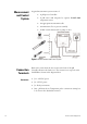
Measurement and Control System A typical measurement system consists of: • A pH process Controller • A pH sensor with integrated or separate Pt100/Pt1000 temperature sensor • An appropriate measurement cable • An immersion, flow or process assembly • A final control element such as pump or valve Figure 2–1. Measurement and Control System Connection Terminals Connectors: 4 Remove the screws from the four corners at the back of the pH Controller. Remove the back cover.
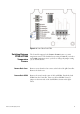
Figure 2–2. Outer Side of Back PCBA Switching Between PT100 & PT1000 Temperature Sensors The Controller supports both Pt100 & Pt1000 (2-wire or 3-wire) temperature sensors. The default factory setting is Pt100. If you need to use Pt1000 temperature sensor, you have to change the jumper setting (J7) as described below. Remove Back Cover Remove screws from the four corners at the back of the pH Controller. Remove the back cover. Remove Back PCBA Remove the screw located center of the back PCBA.
Figure 2–3. Inner Side of Back PCBA Set Jumper J7 6 Set the J7 jumper to required sensor (Pt100 or Pt1000) type.
Connecting pH/ORP Electrode 1. If the pH/ORP electrode has a BNC connector, remove the BNC connector from the cable. NOTE: Oakton Instruments offers an optional ‘BNC to Spade Lug adapter’ (Order code: 05994-90) that can be used with pH/ORP electrode without removing the BNC connector. 2. Strip the insulation of the cable so that the bare wires are exposed enough for connection as shown in diagram below. Figure 2–4.
Installation Mechanical Dimensions Figure 2–5. Frontal View Figure 2–6.
Wall Mount Figure 2–7. Panel Mount Figure 2–8.
Figure 2–9.
Display & Keypad Display Overview The Liquid Crystal Display (LCD) of Alpha pH 560 Controller has two alpha-numerical displays (Upper and a Lower). • Upper display: Measured pH, mV or relative mV value are displayed when the Controller is in normal operation (measurement) mode. • Lower display: Measured temperature value is displayed when the Controller is in normal operation (measurement) mode.
Status Annunciators READY Appears when the reading is stable HOLD Appears in Setup mode and Calibration mode to indicate that the relay function is frozen Appears when Automatic Temperature Compensation (ATC) is enabled. ATC Not visible when Manual Temperature Compensation (MTC) is enabled. Flashes if the temperature probe is faulty in its ATC mode. (Refer Page 26) ERR Appears when an error occurs Electrode annunciator.
Key Functions Figure 2–11. The Liquid Crystal Display (LCD) of Alpha pH 560 Controller has two alpha-numerical displays (Upper and a Lower). CAL Enter Calibration mode Enter Setup mode ENT Access sub screens (parameters) within a group of settings in Setup mode Confirm (save) setup parameters and numerical values Start/Confirm calibration in Calibration mode. Select a group of settings in Setup mode. Select parameters and increment/decrement numerical values in Setup and Calibration modes.
Chapter 3 Operation Measurement Mode When the pH Controller is powered on, the display shows all the LCD segments briefly, and then automatically enters into the Measurement mode. Figure 3–12. The mode indicator ‘MEAS’ at the top of the display indicates that the pH Controller is in Measurement mode; ‘MEAS’ blinks when in Symmetric mode. The upper alpha-numerical display shows the measured pH or mV value, while the lower display shows the temperature value.
Menu Overview Figure 3–13.
Chapter 4 Calibration Mode Preparing the Controller & Electrode for Calibration Before starting calibration, make sure that the pH Controller is in appropriate measurement mode (pH or ORP). When the Controller is switched on, it starts up with the measurement mode last used. For example, if the pH Controller is switched off in ORP measurement mode, it starts up in ORP mode when it is switched on. (Refer Page 5.
NOTES: pH Calibration For USA Standard Buffer • To exit calibration mode at any time during calibration, Press ▲ and ▼ keys simultaneously (escape). The pH Controller returns to the measurement mode and the old calibration values remain active • The calibration is always carried out in the units of measurement (pH or mV), selected in setup mode The pH Controller is capable of calibration of up to 2 points using USA or NIST pH buffer standards.
2 Place the electrode in pH 7.00 buffer. Immerse the temperature probe in the buffer solution if ATC mode is enabled. Immerse the potential matching pin in the buffer if symmetrical mode is enabled. The buffer annunciator appears in LCD. Lower display shows pH 7.00 (USA standard buffer). Upper display shows the current uncalibrated pH reading. Allow the reading to stabilize. LCD shows ‘READY’ annunciator when the reading is stable. Press CAL key to confirm the reading. 3 The calibration is completed.
Place the electrode in pH 7.00 buffer. Immerse the temperature probe in the buffer solution if ATC mode is enabled. Immerse the potential matching pin in the buffer if symmetrical mode is enabled. The buffer annunciator appears in LCD. Lower display shows pH 7.00 (USA standard buffer). Upper display shows the current uncalibrated pH reading. Allow the reading to stabilize. LCD shows ‘READY’ annunciator when the reading is stable. 2 Press ENT key to confirm the reading.
calibration mode, the pH Controller reverts back to ‘process temperature’. For NIST Buffer Make sure that the pH Controller is set to accept NIST standard buffer in the Setup mode. (Refer Page 16) The factory default is USA standard. It is recommended that you perform 2-point calibration at room temperature (25 oC), starting with the first buffer at pH 6.86 followed by any other buffer value. (pH 4.01, 1.68, 9.18 or 12.45) 1-Point Calibration: Figure 4–17.
Figure 4–18. NIST Buffer 2-Point Calibration 1 From pH measurement mode press CAL key to enter calibration mode as described in page 16. The LCD shows ‘CAL PH’. Press ENT key to begin first calibration point. 2 Place the electrode in pH 6.86 buffer. Immerse the temperature probe in the buffer solution if ATC mode is enabled. Immerse the potential matching pin in the buffer if symmetrical mode is enabled. The buffer annunciator appears in LCD. Lower display shows pH 6.86 (NIST standard buffer).
Press ENT key to exit from the calibration. 5 The pH Controller reverts to pH measurement mode. NOTES: • To exit from pH calibration mode without confirming calibration, Press ▲ and ▼ keys together • When confirming the buffer measurement, if the measured pH value is not within ±1.00pH from selected buffer value, the electrode annunciator blinks and ERR indicator appears in the display. This error can also occur if non-standard buffers are used or the electrode has worn out.
ORP value of the solution. Allowable range: -150mV to 150mV. Temperature Calibration Thermo Scientific Alpha pH 560 3 Press ENT key to confirm the value. 4 The pH Controller reverts to ORP measurement mode. Calibrate temperature probe only if temperature value displayed on the pH Controller is different from that of a calibrated thermometer. Refer to page 26 for further information temperature settings.
Chapter 5 Setup Mode Enter Setup Mode The setup mode allows you to customize the settings of the pH Controller to suite your requirements. While in measurement mode, press the ENT key to access setup mode. LCD shows ‘SETUP’ mode indicator and the first page of setup (OFS – offset settings). Press ▲ or ▼ key to access other pages of the setup mode. Figure 5–20. Setup Menu NOTE: Thermo Scientific Alpha pH 560 To exit setup mode at any time press ▲ or ▼ keys simultaneously (escape).
Electrode Offset Settings NOTE: ‘Electrode Offset Setting’ is not available when the pH Controller is configured for ORP measurement mode. (Refer Page 32 for switching measurement modes) In applications where continuous pH measurement is required, it may not be convenient to remove the electrode for calibration. In such cases, an on-line offset adjustment is recommended. The pH Controller allows you set an offset of up to ± 2.00pH to compensate for errors in the pH electrode.
Controller adjust the lower reading automatically to suit the new offset value. Up to ± 2.00 pH offset is allowed. Press ENT key to confirm the value. The pH Controller reverts to OFS screen. Press ▲ or ▼ key to access other setup screens or press ▲ or ▼ key simultaneously (escape) to return to measurement mode. Temperature Settings Automatic Temperature Compensation (ATC): The pH values other than pH 7.00 are affected by temperature.
Press ▲ or ▼ key to select the desired units for temperature (ºC or ºF). Press ENT key to confirm your selection. 3 Enable/disable ATC: The lower display shows ‘AtC’ and the upper display shows the last configured ATC selection (‘On’ or ‘OFF’). Press ▲ or ▼ key to enable (ATC On) or disable (ATC OFF) automatic temperature compensation. Press ENT key to confirm your selection.
to adjust the upper display to desired calibration temperature. Allowable range: –10.0 to 125.0°C / 14.0 to 257°F. Press ENT key to confirm the calibration temperature. The pH Controller reverts to SET ºCF screen. Press ▲ or ▼ key to access other setup screens or Press ▲ and ▼ key simultaneously (escape) to return to measurement mode. To exit from any intermediate steps, press ▲ and ▼ keys simultaneously (escape). The pH Controller returns to the first screen of temperature settings SET ºCF.
configured set point value, otherwise the default value. Press ▲ or ▼ key to enter the value for set point 1, at which control function of the pH Controller should activate. Press ENT key to confirm your set point value. 3 Select relay function: The upper display shows the last configured relay function (LO = Low or HI=High). Press ▲ or ▼ key to select the desired function. Press ENT key to confirm your selection. NOTE: This parameter lets you choose the relay function.
Press ▲ or ▼ key to access other setup screens or Press ▲ and ▼ key simultaneously (escape) to return to measurement mode. Controller Settings The controller settings allow you to determine the relay type and relay status of the pH Controller. Figure 5–24. Controller Settings 1 From pH (or ORP) measurement mode press ENT key to enter setup mode as described in page 30. The LCD shows the first screen of setup mode (OFS). Press ▲ or ▼ key to select controller settings screen (Cntr).
parameters. Press ENT key to confirm your selection. If Controller type was set to Off (OFF) The pH Controller reverts to Cntr screen. If Controller type was set to On (L.Ct) 3 Select the relay status under Non-Alarm condition: The lower display shows ‘rEL’. The upper display shows the last configured relay status. (‘dEEn’ or ‘En’). Press ▲ or ▼ key to select the desired relay status. EEn: De-energized En: Energized Press ENT key to confirm your selection. The pH Controller reverts to Cntr screen.
1 From pH measurement mode press ENT key to enter setup mode as described in page 24. The LCD shows the first screen of setup mode (OFS). Press ▲ or ▼ key to select buffer settings screen (bUFF). Press ENT key to access buffer settings (bUFF). 2 Selecting buffer group: The lower display shows the last configured buffer group. Press ▲ or ▼ key to select the required buffer group (‘USA’ or ‘nST’). Press ENT key to confirm your selection. The pH Controller reverts to bUFF screen.
Figure 5–26. Configuration Settings 1 From pH (or ORP) measurement mode press ENT key to enter setup mode as described in page 24. The LCD shows the first screen of setup mode (OFS). Press ▲ or ▼ key to select configuration settings screen (Cnfg). Press ENT key to access configuration settings (Cnfg). 2 Enable/disable LCD backlight: The upper display shows ‘LitE’. The lower display shows last configured backlight selection (‘On’ or ‘OFF’).
to their default values. 4 Select operation mode: The upper display shows the last configured operation mode. (‘ASY’ or ‘SY’). Press ▲ or ▼ key to select your desired operational mode. Press ENT key to confirm your selection. 5 Reset to factory defaults: The display shows ‘nO dEF’. Press ▲ or ▼ key to select: nO dEF: Not default reset of the pH Controller. User configured values remain active, when confirmed by pressing ENT key.
Viewing Electrode Properties Each time you calibrate your pH electrode, the pH Controller recalculates slope & offset of the electrode and shown in the LCD at the end of calibration. The setup mode allows you to view slope & offset values at any time. NOTE: When the measurement mode is set to ORP, only the offset value of the electrode is displayed. Figure 5–27. Viewing Electrode Properties 1 From pH (or ORP) measurement mode press ENT key to enter setup mode as described in page 24.
Chapter 6 Technical Specifications Product Technical Specification GENERAL SPECIFICATIONS (a) pH Measuring Range 0.00 to 14.00 pH Resolution 0.01 pH Accuracy ± 0.01 pH (b) mV Measuring Range -1000 to 1000 mV Resolution 1 mV Accuracy ± 1 mV (c) Temperature Measuring range -10.0 to +125.0 oC or +14.0 to +257 o F Resolution 0.1 oC 0.1 oF (Resolution is 0.1 oF up to 199.9 oF and 1 oF for 200 oF and above) Relative accuracy ±0.5 oC ±1.
Product Technical Specification Number of calibration points 1 or 2 points Number of calibration buffers USA: 1.68,4.01, 7.00, 0.01,12.45 NIST: 1.68,4.01, 6.86, 9.18 ,12.45 (b) Temperature Offset Adjustment ± 10 ˚C/ ± 18 ˚F INPUT / OUTPUT Input Asymmetrical / Symmetrical Output 2 SPST Relays DISPLAY LCD 7 segments display with symbols for status information Back light On/Off selectable ELECTRICAL DATA AND CONNECTIONS pH/mV Input Screw Terminal (3.
Chapter 7 List of Accessories Thermo Scientific Controller Replacement and Accessories Item Description Order Code Alpha-pH 560 Controller TSPHCP0560 Combination pH electrode with 5m cable ECARTSO05B Combination pH electrode with PMP and 5m cable ECARGTSO05B Combination pH electrode with PT 100, PMP and 5m cable EC100GTSO05B Combination pH electrode, submersible, with 5m cable ECDA9350605B Combination Gold ORP electrode with PMP and 5m cable ECHTAUTSO05B Combination Platinum ORP electrode wi
NOTE: Eutech Instruments • pH buffer solutions (480 ml bottle) have ±0.01 pH accuracy at 25 °C • pH buffer sachets are individually sealed, single use pouch containing 20 ml of fresh, contamination free calibration solution • pH buffer sachets have ±0.
Chapter 8 Troubleshooting Problem Power on, but no display Cause a) Loose connections b) Incorrect output voltage of the power adaptor Unstable pH reading a) Dirty electrode b) Electrical noise interference Oscillating temperature readings a) Electrical noise interference Slow response a) Dirty / Oily electrode a) No temperature probe connection during ATC mode a) Error in calibration Blinking ATC Blinking electrode annunciator Thermo Scientific Alpha pH 560 Or (pH) a) pH electrode is not conne
Chapter 9 General Information Warranty Return of Goods Guidelines for Returning Unit for Repair Thermo Fisher Scientific warrants this product to be free from significant deviations in material and workmanship for a period of one year from the date of purchase. If repair is necessary and not the result of abuse or misuse within the warranty period, please return by freight pre-paid and amendment will be made without any charge. Eutech Instrument Customer Service Dept.
Appendices Appendix 1 pH Buffer Values at Various Temperatures 42 The following table shows the various pH values at different temperature of the solution during calibration. Temperature pH 4.01 pH 6.86 pH 7.00 pH 9.18 pH 10.01 (oC) 0 4.01 6.98 7.12 9.47 10.32 5 4.01 6.95 7.09 9.38 10.25 10 4.00 6.92 7.06 9.32 10.18 15 4.00 6.90 7.04 9.27 10.12 20 4.00 6.88 7.02 9.22 10.06 25 4.01 6.86 7.00 9.18 10.01 30 4.01 6.85 6.99 9.14 9.97 35 4.02 6.84 6.98 9.10 9.93 40 4.03 6.84 6.97 9.07 9.89 45 4.04 6.83 6.97 9.
Index: Error! No text of specified style in document. Appendix 2 Graphical Representation of the Function of Hysteresis The relay of the pH Controller activates when the set-point is reached (forward direction). In the reverse direction, it does not de-activate when the value reaches the set-point. Instead, it continues to be active till the value reaches the amount set by the Hysteresis band. Example: You have set your high set point at pH 10.0 and your hysteresis value at pH 0.5.
Appendix 4 Abbreviations Used in LCD Abbreviation ASy Asymmetrical mode AtC Automatic Temperature Compensation bUFF Buffer CAL Calibration C.ºC Calibration temperature CdAt Electrode properties CnFg Configuration Cntr Controller dEF Default values dEEn De-energized En Energized FCt Factory (defaults) HI High limit HyS Hysteresis LitE Backlight LO Low limit OFS Offset OF.d Off delay On.
Index: Error! No text of specified style in document.
46 Thermo Scientific Alpha pH 560
Water Analysis Instruments North America 166 Cummings Center Beverly, MA 01915 USA Toll Free: 1-800-225-1480 Tel: 1-978-232-6000 Dom. Fax: 1-978-232-6015 Int’l Fax: 978-232-6031 Europe P.O. Box 254, 3860 AG Nijkerk Wallerstraat 125K, 3862 CN Nijkerk, Netherlands Tel: (31) 033-2463887 Fax: (31) 033-2460832 Asia Pacific Blk 55, Ayer Rajah Crescent #04-16/24, Singapore 139949 Tel: 65-6778-6876 Fax: 65-6773-0836 www.thermo.com/process © 2009 Thermo Fisher Scientific Inc. All rights reserved.