Instruction Manual αlpha TDS 190 1/8 DIN Total Dissolved Solids Controller with Temperature display and Transmitter Technology Made Easy ...
PREFACE This manual serves to explain the use of the αlpha TDS 190 controller/transmitter. This manual functions in two ways: first, as a step-by-step guide to help you operate the meter; second, it serves as a handy reference guide. This manual is written to cover as many anticipated applications of the αlpha TDS 190 controller/transmitter as possible.
TABLE OF CONTENTS 1 INTRODUCTION 2 SAFETY INFORMATION 2 3 OVERVIEW 3 4 1 3.1 FRONT PANEL 3 3.2 BACK PANEL 4 3.3 WIRING 5 3.4 PANEL-MOUNTING THE CONTROLLER 5 3.5 FERRITE ASSEMBLY 6 MEASUREMENT MODE 7 4.1 MEASUREMENT MODE DISPLAY 7 4.2 SET POINTS ADJUSTMENTS 8 5 PASSWORD 6 TDS CALIBRATION 11 7 TEMPERATURE CALIBRATION 13 8 SETUP MODE 14 8.1 GENERAL INFORMATION 14 8.2 SETUP MODE OVERVIEW 15 8.3 SET POINT 1 – P1.0 16 8.4 SET POINT 2 – P2.0 18 8.
1 INTRODUCTION Thank you for purchasing the αlpha TDS 190 ⅛ DIN TDS Controller. This controller is part of a series of quality process controllers available from Eutech Instruments. These sturdy, economical TDS controllers are designed with the features and reliability of a much more expensive instrument.
2 SAFETY INFORMATION The Eutech Controller / Transmitter shall be installed and operated only in the manner specified in the Instruction manual. Only skilled, trained or authorized person should carry out installation, setup and operation of the instrument. Before powering up the unit, make sure that power source it is connected to, is as specified in the top label. Failure to do so may result in a permanent damage to the unit. The unit has live and exposed parts inside.
3 OVERVIEW 3.1 Front Panel The front panel consists of a 4-digit LED display, 8 LED annunciators and 4 keys. Annunciators 1. REL 1 2. REL 2 3. MEAS 4. CAL 5. SETUP 6. ppm 7. oC 8. ppt Displayed when Relay 1 is activated Displayed when Relay 2 is activated Displayed in measurement mode Displayed in calibration mode Displayed in setup mode Unit of the displayed parameter (parts per million) Unit of the displayed parameter (temperature) Unit of the displayed parameter (parts per thousand) Keys 9. MODE 10.
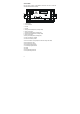
3.2 Back Panel The back panel consists of three different connectors that can be used with removable terminal blocks (included): PT100 NC 10 9 8 7 6 IN NC RELAY2 SENSE 11 - CON - 4 - 20mA 12 + CON GND + 4 - 20mA Caution RELAY1 NC 19 18 17 16 15 14 13 21 20 5 4 NC N L 3 2 1 1. VAC live wire 2. VAC neutral wire 3. unused 4. unused 5. Relay 2 deactivated position (normally closed) 6. Relay 2 center pole 7. Relay 2 activated position (normally open) 8.
3.3 Wiring Caution: Ensure electrical mains are disconnected before proceeding. 1. Connect the power supply to the three-pin terminal block VAC live wire = 1 VAC neutral wire = 2 VAC protective ground wire = 20 OR 21 αlpha TDS 190 controller accepts voltages from 85 to 260 VAC, 50/60 Hz or DC. • • • 2. Connect the Pt 100 leads to terminals 13 to 15 of the seven-pin terminal block. Either wire can be connected to either terminal. Terminals 13 and 14 must be shunted unless using a 3-wire RTD.
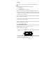
Wall panel approx. 154.20 Catch Catch Threaded rod Threaded rod SIDE VIEW approx. 100 TOP VIEW 3.5 Ferrite Assembly The power cable (L, N & E) needs to be connected to the instrument with two turns through the Split Ferrite which is supplied as an accessory with the instrument. It is strongly suggested that the Ferrite element supplied as a standard accessory be installed as described below.
4 MEASUREMENT MODE The αlpha TDS 190 controller is capable of taking TDS measurement with Automatic (ATC) or Manual (MTC) Temperature Compensation. The measurements are displayed distinguishingly by the annunciators on the front panel. 4.1 Measurement mode display Press the MODE key to toggle between TDS and Temperature measurement mode. Conductivity Measurement Mode The controller displays the selected TDS range number, R X (X ranges from 1 to 8), for 2 seconds before displaying the TDS measurement.
4.2 Set Points Adjustments You can make quick set points adjustments with the direct access of the Set Points adjustment modes (SP1 and/or SP2). By just pressing the SP1/▲ or SP2/▼key, you can enter the Set Point adjustment mode and set a new TDS value that will cause your controller to activate. Set Point 1 (SP1) adjustment mode This lets you adjust the TDS value in Set Point 1. If this value is crossed, the set point relay 1 LED will light. 1. 2. 3. Press the SP1/▲ key. The screen will scroll P1.
5 PASSWORD The Setup mode is to be accessed by entering a password code. The direct accessed Set Point adjustment mode (SP1 and SP2) and the Calibration mode can also be accessed through this password code procedure. The αlpha TDS 190 controller features two separate passwords: • TDS and Temperature calibration mode password = 011 • Setup program password = 022 To enter the password: 1. Press the MODE key, and within 1 second, press the CAL/ENTER key. The display reads P.WRD. 2. Press ENTER again.
P. P.000 P.000 P.010 P.020 P.011 P.022 P.011 P.
6 TDS CALIBRATION IMPORTANT: When Calibration mode is entered, controller automatically goes into a “HOLD” mode where the 4-20 mA output freezes and relays are de-activated (if it was in an activated condition). Upon return to measurement mode, both 4-20mA output and relay activities resume, depending on settings. The αlpha TDS 190 controller includes 8 TDS measurement ranges. One-point slope calibration is possible, in each range.
4. If any of the two conditions mentioned above is not satisfied, controller will display ERR1, blinking. 5. If calibration is successful, Controller displays DONE, blinking. Press ENTER to revert to TDS measurement mode (Relays and 4-20 mA output resume previous settings). NOTE: To clear the ERR1 display and return to calibration mode, press ▲/ ▼ keys together. 509 500 ENTER done ENTER Notes: You can view the calibrated TDS value from Setup program. See Setup program P5.0.
7 TEMPERATURE CALIBRATION IMPORTANT: When Calibration mode is entered, controller automatically goes into a “HOLD” mode where the 4-20 mA output freezes and relays are de-activated (if it was in an activated condition). Upon return to measurement mode, both 4-20mA output and relay activities resume, depending on settings. This controller features selectable Automatic Temperature Compensation (ATC) or Manual Temperature Compensation (MTC). ATC: ATC mode requires a Pt 100 temperature element.
8 SETUP MODE 8.1 General Information IMPORTANT: When Setup mode is entered, controller automatically goes into a “HOLD” mode where the 4-20 mA output freezes and relays are de-activated (if it was in an activated condition). Upon return to measurement mode, both 4-20mA output and relay activities resume, depending on settings. To enter setup mode: 1. Key in password “022” using method described in section 5. 2. Press ▲or ▼keys to display various sub-menus shown here. 3.
8.2 Setup mode overview P1.0: Set Point 1 P1.1: select relay 1 set point value P1.2: select relay 1 as low or high set point P1.3: set relay 1 hysteresis value P2.0: Set Point 2 P2.1: select relay 2 set point value P2.2: select relay 2 as low or high set point P2.3: set relay 2 hysteresis value P3.0: Range P3.1: select measurement range (with the corresponding cell constant value). Eight measurement ranges are available. P4.0: Temperature Data P4.1: select ATC or MTC P4.
8.3 Set Point 1 – P1.0 Setup program P1.0 allows you to set parameters for relay 1. P1.1: select relay 1 set point value P1.2: select relay 1 as low or high set point P1.3: set relay 1 hysteresis value (dead band) P1.0 SP 1 P1.1 SP 1 100.0 P1.2 P1.3 SP 1 HYSt LOW . 100 HIGH Press ▲and ▼keys together (ESCAPE) at anytime, to leave Setup mode and return to Measurement mode. P1.1: Select relay set point value Set the TDS value that will activate Relay 1.
P1.3: Set Hysteresis value Hysteresis prevents rapid contact switching if measured value is fluctuating near the set point. Once activated, relay will not de-activate until measured value reaches set point plus hysteresis value. Example: Low set point is 100.0 ppm and hysteresis 10.0 ppm, relay will activate when value drops below 100.0 ppm, but will not de-activate till measured TDS value rises above 110.0 ppm. Default hysteresis value is 5% of full scale.
8.4 Set Point 2 – P2.0 Setup program P2.0 allows you to set parameters for relay 2. P2.1: select relay 2 set point value P2.2: select relay 2 as low or high set point P2.3: set relay 2 hysteresis value (dead band) P2.0 SP 2 P2.1 SP 2 900 P2.2 P2.3 SP 2 HYSt LOW 50 HIGH Press ▲and ▼keys together (ESCAPE) at anytime, to leave Setup mode and return to Measurement mode. P2.1: Select relay set point value Set the TDS value that will activate Relay 2.
P2.3: Set Hysteresis value Hysteresis prevents rapid contact switching if measured value is fluctuating near the set point. Once activated, relay will not de-activate until measured value reaches set point plus hysteresis value. Example: High set point is 900 ppm and hysteresis 50 ppm, relay will activate when value rises above 900 ppm, but will not de-activate till measured TDS value drops below 850 ppm. Default hysteresis value is 5% of full scale.
8.5 Measurement Range Selection – P3.0 Setup program P3.0 is for selecting the range of measurement. P3.1: select measurement range and corresponding cell constant P3.0 RNGE P3.1 1000 K 10 . Press ▲and ▼keys together (ESCAPE) at anytime, to leave the Setup mode and return to Measurement mode. P3.1: Select Measurement Range Set controller to the specific range of measurement. Ensure the cell you have connected to the controller has the same cell constant as that stated in the range. 1. 2. 3. 4.
8.6 Configure Temperature Settings – P4.0 Setup program P4.0 is for selecting ATC or MTC, set temperature coefficient values, and select normalization temperature P4.1: ATC or MTC mode (default : ATC mode) P4.2: set temperature coefficient (default : 2.10 %) P4.3: set Normalization temperature (default : 25.0 oC) P4.0 TEMP P4.1 MODE ATC MTC P4.2 COEF 2.0 P4.3 NORM 25.0 P4.1: Selecting ATC or MTC 1. Key in the password “022” as per procedure in Section 5. 2. Press ▲key until screen displays P4.
8.7 Viewing TDS Calibration Data – P5.0 Program 5 is a “view only” option, which displays the value at which calibration was performed. P5.1: view Calibrated TDS value (if no calibration performed for this range, controller displays ‘- - - - ‘). These parameters will change each time you recalibrate the controller. P5.0 CL P5.1 CAL 300 Press ▲and ▼keys together (ESCAPE) at anytime, to leave the Setup mode and return to Measurement mode. P5.0: Viewing Calibrated TDS data 1.
8.8 Viewing TDS/ Temperature Electrode Data – P6.0 Program 6 has two “view only” options that let you check the electrode parameters for diagnostic purposes. P6.1: view revised cell constant value of electrode P6.2: view temperature probe offset (ATC on only) These parameters will change each time you recalibrate the controller. P6.0 elec P6.1 FCTR 1.000 P6.2 t.ofs 0.0 Press ▲and ▼keys together (ESCAPE) at anytime, to leave the Setup mode and return to Measurement mode. P6.
8.9 Setting TDS Factor – P7.0 Program 7 allows the TDS factor to be selected, depending on the application. P .0 tds . 0 0 P7.1: Setting TDS Factor 1. Key in the password “022” as per procedure in Section 5. 2. Press ▲key until screen displays P7.0 and TDS. Press ENTER. 3. Screen will scroll P7.1, ‘FACT.’ then TDS factor. (Default is 0.70) 4. Press the ▲or ▼keys to change TDS factor (0.40 to 1.0). Press ENTER to confirm. 5. Press ▲and ▼keys together (ESCAPE) to return to P7.0.
8.10 Controller Reset – P8.0 Program 8 gives an option to reset the controller to factory default values. • TDS range remains unchanged based on last selected range • All calibration data and TDS factor are reset • SP 1 is reset to 10 % of full scale and LOW • SP 2 is reset to 90 % of full scale and HIGH • Hysteresis for both set points is reset to 5 % of full scale • Temperature compensation mode remains unchanged (ATC or MTC) • In MTC mode, temperature value is reset to 25.
9 RELAYS The αlpha TDS 190 features two SPDT non-powered relays; rated for 6A at 110 VAC, 250 VAC maximum. When your process exceeds the set parameters of a relay set point, the REL 1 or REL 2 indicator will light up. To set parameters for relay 1 and relay 2, see Setup programs P1.0 and P2.0. 10 TRANSMITTER FUNCTION If remote data logging is required, a 4-20 mA current loop can be connected.
11 SPECIFICATIONS TDS Range 0.00 – 10.00 ppm 0.0 – 100.0 ppm 0.0 – 100.0 ppm 0 – 1000 ppm 0.00 – 5.00 ppt 0.00 – 10.00 ppt 0.0 – 100.0 ppt 0.0 – 100.
12 ACCESSORIES Product Description Conductivity cell, Epoxy body, Graphite sensor, w/3-wire Pt100, k = 0.1 Conductivity cell, Epoxy body, Graphite sensor, w/3-wire Pt100, k = 1.0 Code no. ECCONSEN89X ECCONSEN88X Conductivity 2 Cell type probe, 0.1 - 200µS; Cell constant, K=0.1 with integrated Pt 100, Material SS316 and 25ft cable (open-ended) EC-CS10-0-1S Conductivity 2 Cell type probe, up to 200 mS; Cell constant, K=1.
Appendix 1: Simple Explanation on the Function of Hysteresis SP1 Set to LO SP2 Set to HI RELAY ON RELAY OFF 100 110 SP1 850 900 ppm SP2 FORWARD DIRECTION REVERSE DIRECTION The controller relay activates when the setpoint is reached. In the reverse direction, it does not de-activate when the value reaches the set-point. Instead, it continues to be active till the value reaches the amount set by the Hysteresis band.
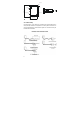
Appendix 3: External Relays The relays on the αlpha TDS 190 series controller are rated for 6 amps at 110 VAC and can be wired directly to your final control element (provided its power requirements does not exceed this). However, to preserve the life of your controller, or if higher power is needed, it is recommended that you use the controller relay to drive an external relay. Diagram below shows a typical installation. Wiring should be changed appropriately if normally closed (N.C.) operation is desired.
13 GENERAL INFORMATION Warranty Eutech Instruments warrants this product to be free from significant deviations in material and workmanship for a period of one year from the date of purchase. If repair is necessary and has not been the result of abuse or misuse within the warranty period, please return by freight pre-paid and amendment will be made without any charge. Eutech Instruments’ Customer Service Dept. will determine if product problem is due to deviations or customer abuse.
For more information on Eutech Instruments products, contact your nearest Eutech Instruments distributor or visit our website listed below: Manufactured by: Eutech Instruments Pte Ltd. Blk 55, Ayer Rajah Crescent, #04-16/24 Singapore 139949 Tel: (65) 6778 6876 Fax: (65) 6773 0863 E-mail: marketing@eutechinst.com Web-site: http://www.eutechinst.